Infiniti FX35 / FX45. Manual - part 27


  Index      Infiniti     Infiniti FX35 / FX45 (S50) - service repair manual 2008 year


Search            


Content   ..  25  26  27  28   ..


Infiniti FX35 / FX45. Manual - part 27


AT-36

< SERVICE INFORMATION >

A/T CONTROL SYSTEM

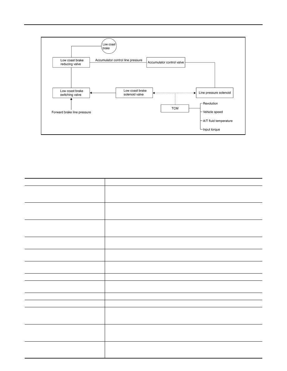
Therefore, the low coast brake solenoid is operated to prevent the forward one-way clutch from idling and
the engine brake is operated in the same manner as conventionally.

• The operation of the low coast brake solenoid switches the low coast brake switching valve and controls the

coupling and releasing of the low coast brake.
The low coast brake reducing valve controls the low coast brake coupling force.

Control Valve

INFOID:0000000001327142

FUNCTION OF CONTROL VALVE 

SCIA1520E

Name

Function

Torque converter regulator valve

In order to prevent the pressure supplied to the torque converter from being excessive, 
the line pressure is adjusted to the optimum pressure (torque converter operating pres-
sure).

Pressure regulator valve
Pressure regulator plug
Pressure regulator sleeve

Adjusts the oil discharged from the oil pump to the optimum pressure (line pressure) for 
the driving state.

Front brake control valve

When the front brake is coupled, adjusts the line pressure to the optimum pressure (front 
brake pressure) and supplies it to the front brake. (In 1st, 2nd, 3rd, and 5th gears, adjusts 
the clutch pressure.)

Accumulator control valve

Adjusts the pressure (accumulator control pressure) acting on the accumulator piston 
and low coast reducing valve to the pressure appropriate to the driving state.

Pilot valve A

Adjusts the line pressure and produces the constant pressure (pilot pressure) required 
for line pressure control, shift change control, and lock-up control.

Pilot valve B

Adjusts the line pressure and produces the constant pressure (pilot pressure) required 
for shift change control.

Low coast brake switching valve

During engine braking, supplies the line pressure to the low coast brake reducing valve.

Low coast brake reducing valve

When the low coast brake is coupled, adjusts the line pressure to the optimum pressure 
(low coast brake pressure) and supplies it to the low coast brake.

N-R accumulator

Produces the stabilizing pressure for when N-R is selected.

Direct clutch piston switching valve

Operates in 4th gear and switches the direct clutch coupling capacity.

High and low reverse clutch control valve

When the high and low reverse clutch is coupled, adjusts the line pressure to the opti-
mum pressure (high and low reverse clutch pressure) and supplies it to the high and low 
reverse clutch. (In 1st, 3rd, 4th and 5th gears, adjusts the clutch pressure.)

Input clutch control valve

When the input clutch is coupled, adjusts the line pressure to the optimum pressure (in-
put clutch pressure) and supplies it to the input clutch. (In 4th and 5th gears, adjusts the 
clutch pressure.)

Direct clutch control valve

When the direct clutch is coupled, adjusts the line pressure to the optimum pressure (di-
rect clutch pressure) and supplies it to the direct clutch. (In 2nd, 3rd, and 4th gears, ad-
justs the clutch pressure.)

A/T CONTROL SYSTEM

AT-37

< SERVICE INFORMATION >

D

E

F

G

H

I

J

K

L

M

A

B

AT

N

O

P

FUNCTION OF ATF PRESSURE SWITCH 

TCC control valve
TCC control plug
TCC control sleeve

Switches the lock-up to operating or released. Also, by performing the lock-up operation 
transiently, lock-up smoothly.

Torque converter lubrication valve

Operates during lock-up to switch the torque converter, cooling, and lubrication system 
oil passage.

Cool bypass valve

Allows excess oil to bypass cooler circuit without being fed into it.

Line pressure relief valve

Discharges excess oil from line pressure circuit.

N-D accumulator

Produces the stabilizing pressure for when N-D is selected.

Manual valve

Sends line pressure to each circuit according to the select position. The circuits to which 
the line pressure is not sent drain.

Name

Function

Name

Function

ATF pressure switch 2 (LC/B)

Detects any malfunction in the low coast brake hydraulic pressure. When it detects any 
malfunction, it puts the system into fail-safe mode.

AT-38

< SERVICE INFORMATION >

ON BOARD DIAGNOSTIC (OBD) SYSTEM

ON BOARD DIAGNOSTIC (OBD) SYSTEM

Introduction

INFOID:0000000001327143

The A/T system has two self-diagnostic systems.
The first is the emission-related on board diagnostic system (OBD-II) performed by the TCM in combination
with the ECM. The malfunction is indicated by the MIL (malfunction indicator lamp) and is stored as a DTC in
the ECM memory but not the TCM memory.
The second is the TCM original self-diagnosis indicated by the A/T CHECK indicator lamp. The malfunction is
stored in the TCM memory. The detected items are overlapped with OBD-II self-diagnostic items. For detail,
refer to 

AT-84, "CONSULT-III Function (TRANSMISSION)"

.

OBD-II Function for A/T System

INFOID:0000000001327144

The ECM provides emission-related on board diagnostic (OBD-II) functions for the A/T system. One function
is to receive a signal from the TCM used with OBD-related parts of the A/T system. The signal is sent to the
ECM when a malfunction occurs in the corresponding OBD-related part. The other function is to indicate a
diagnostic result by means of the MIL (malfunction indicator lamp) on the instrument panel. Sensors, switches
and solenoid valves are used as sensing elements.
The MIL automatically illuminates in “One or Two Trip Detection Logic” when a malfunction is sensed in rela-
tion to A/T system parts.

One or Two Trip Detection Logic of OBD-II

INFOID:0000000001327145

ONE TRIP DETECTION LOGIC

If a malfunction is sensed during the first test drive, the MIL will illuminate and the malfunction will be stored in
the ECM memory as a DTC. The TCM is not provided with such a memory function.

TWO TRIP DETECTION LOGIC

When a malfunction is sensed during the first test drive, it is stored in the ECM memory as a 1st trip DTC
(diagnostic trouble code) or 1st trip freeze frame data. At this point, the MIL will not illuminate. — 1st trip
If the same malfunction as that experienced during the first test drive is sensed during the second test drive,
the MIL will illuminate. — 2nd trip
The “Trip” in the “One or Two Trip Detection Logic” means a driving mode in which self-diagnosis is performed
during vehicle operation.

OBD-II Diagnostic Trouble Code (DTC)

INFOID:0000000001327146

HOW TO READ DTC AND 1ST TRIP DTC

DTC and 1st trip DTC can be read by the following methods.
(

 with CONSULT-III or 

 GST) CONSULT-III or GST (Generic Scan Tool) Examples: P0705, P0720 etc.

These DTC are prescribed by SAE J2012.
(CONSULT-III also displays the malfunctioning component or system.)
• 1st trip DTC No. is the same as DTC No.
• Output of the diagnostic trouble code indicates that the indicated circuit has a malfunction. How-

ever, in case of the Mode II and GST, they do not indicate whether the malfunction is still occurring or
occurred in the past and returned to normal.
CONSULT-III can identify them as shown below, therefore, CONSULT-III (if available) is recom-
mended.

- DTC or 1st trip DTC of malfunction is displayed in SELF-DIAGNOSTIC RESULTS mode for “ENGINE” with

CONSULT-III. Time data indicates how many times the vehicle was driven after the last detection of a DTC.

- If the DTC is being detected currently, the time data will be “0”.
- If a 1st trip DTC is stored in the ECM, the time data will be “1t”.

Freeze Frame Data and 1st Trip Freeze Frame Data

The ECM has a memory function, which stores the driving condition such as fuel system status, calculated
load value, engine coolant temperature, short term fuel trim, long term fuel trim, engine speed and vehicle
speed at the moment the ECM detects a malfunction.
Data which are stored in the ECM memory, along with the 1st trip DTC, are called 1st trip freeze frame data,
and the data, stored together with the DTC data, are called freeze frame data and displayed on CONSULT-III
or GST. The 1st trip freeze frame data can only be displayed on the CONSULT-III screen, not on the GST. For

ON BOARD DIAGNOSTIC (OBD) SYSTEM

AT-39

< SERVICE INFORMATION >

D

E

F

G

H

I

J

K

L

M

A

B

AT

N

O

P

detail, refer to 

EC-117, "CONSULT-III Function (ENGINE)"

 (for VQ35DE) or 

EC-695, "CONSULT-III Function

(ENGINE)"

 (for VK45DE).

Only one set of freeze frame data (either 1st trip freeze frame data of freeze frame data) can be stored in the
ECM. 1st trip freeze frame data is stored in the ECM memory along with the 1st trip DTC. There is no priority
for 1st trip freeze frame data and it is updated each time a different 1st trip DTC is detected. However, once
freeze frame data (2nd trip detection/MIL on) is stored in the ECM memory, 1st trip freeze frame data is no
longer stored. Remember, only one set of freeze frame data can be stored in the ECM. The ECM has the fol-
lowing priorities to update the data.

Both 1st trip freeze frame data and freeze frame data (along with the DTC) are cleared when the ECM mem-
ory is erased.

HOW TO ERASE DTC

The diagnostic trouble code can be erased by CONSULT-III, GST or ECM DIAGNOSTIC TEST MODE as
described following.
• If the battery cable is disconnected, the diagnostic trouble code will be lost within 24 hours.
• When you erase the DTC, using CONSULT-III or GST is easier and quicker than switching the mode

selector on the ECM.

The following emission-related diagnostic information is cleared from the ECM memory when erasing DTC
related to OBD-II. For details, refer to 

EC-55, "Emission-Related Diagnostic Information"

 (for VQ35DE) or 

EC-

633, "Emission-related Diagnostic Information"

 (for VK45DE).

• Diagnostic trouble codes (DTC)
• 1st trip diagnostic trouble codes (1st trip DTC)
• Freeze frame data
• 1st trip freeze frame data
• System readiness test (SRT) codes
• Test values

 HOW TO ERASE DTC (WITH CONSULT-III)

1.

The emission related diagnostic information in the TCM and ECM can be erased by selecting “ALL Erase”
in the “Description” of “FINAL CHECK” mode with CONSULT-III.

 HOW TO ERASE DTC (WITH GST)

1.

If the ignition switch stays ON after repair work, be sure to turn ignition switch OFF once. Wait at least 10
seconds and then turn it ON (engine stopped) again.

2.

Perform “TCM SELF-DIAGNOSTIC PROCEDURE (No Tools)”. Refer to 

AT-91, "Diagnosis Procedure

without CONSULT-III"

. (The engine warm-up step can be skipped when performing the diagnosis only to

erase the DTC.)

3.

Select Mode 4 with Generic Scan Tool (GST). For details, refer to 

EC-125, "Generic Scan Tool (GST)

Function"

 (for VQ35DE) or 

EC-704, "Generic Scan Tool (GST) Function"

 (for VK45DE).

 HOW TO ERASE DTC (NO TOOLS)

The A/T CHECK indicator lamp is located on the instrument panel.

1.

If the ignition switch stays ON after repair work, be sure to turn ignition switch OFF once. Wait at least 10
seconds and then turn it ON (engine stopped) again.

2.

Perform “TCM SELF-DIAGNOSTIC PROCEDURE (No Tools)”. Refer to 

AT-91, "Diagnosis Procedure

without CONSULT-III"

. (The engine warm-up step can be skipped when performing the diagnosis only to

erase the DTC.)

3.

Perform “OBD-II SELF-DIAGNOSTIC PROCEDURE (No tools)”. Refer to 

EC-55, "Emission-Related

Diagnostic Information"

 (for VQ35DE) or 

EC-633, "Emission-related Diagnostic Information"

 (for

VK45DE).

Priority

Items

1

Freeze frame data

Misfire — DTC: P0300 - P0306
Fuel Injection System Function — DTC: P0171, P0172, P0174, P0175

2

Except the above items (Includes A/T related items)

3

1st trip freeze frame data


Content   ..  25  26  27  28   ..