Infiniti FX35, FX50 (S51). Manual - part 872


  Index      Infiniti     Infiniti FX35, FX50 (S51) - service repair manual 2010 year


Search            


Content   ..  870  871  872  873   ..


Infiniti FX35, FX50 (S51). Manual - part 872


P1551, P1552 BATTERY CURRENT SENSOR

EC-1029

< DTC/CIRCUIT DIAGNOSIS >

[VK50VE]

C

D

E

F

G

H

I

J

K

L

M

A

EC

N

P

O

• Harness connectors F10, E10
• Harness for open or short between battery current sensor and ECM

>> Repair open circuit, short to ground or short to power in harness or connectors.

11.

CHECK BATTERY CURRENT SENSOR INPUT SIGNAL CIRCUIT FOR OPEN AND SHORT

1.

Check the continuity between battery current sensor harness connector and ECM harness connector.

2.

Also check harness for short to ground and short to power.

Is the inspection result normal?

YES

>> GO TO 13.

NO

>> GO TO 12.

12.

DETECT MALFUNCTIONING PART

Check the following.
• Harness connectors F10, E10
• Harness for open or short between battery current sensor and ECM

>> Repair open circuit, short to ground or short to power in harness or connectors.

13.

CHECK BATTERY CURRENT SENSOR

Refer to 

EC-1029, "Component Inspection"

.

Is the inspection result normal?

YES

>> GO TO 14.

NO

>> Replace battery negative cable assembly.

14.

CHECK INTERMITTENT INCIDENT

Refer to 

GI-36, "Intermittent Incident"

.

>> INSPECTION END

Component Inspection

INFOID:0000000005237522

1.

CHECK BATTERY CURRENT SENSOR

1.

Turn ignition switch OFF.

2.

Reconnect harness connectors disconnected.
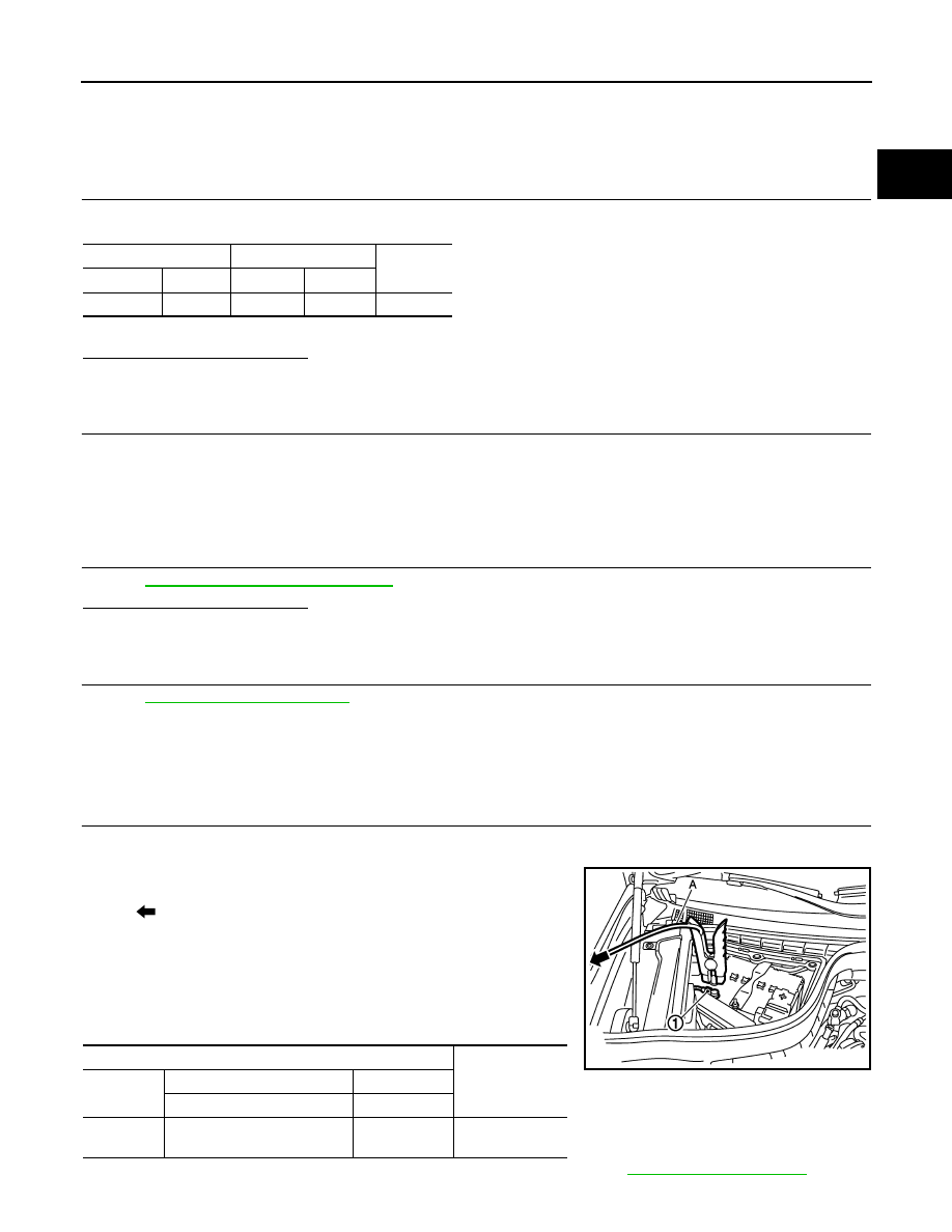
3.

Disconnect battery negative cable (1).

4.

Install jumper cable (A) between battery negative terminal and
body ground.

5.

Turn ignition switch ON.

6.

Check the voltage between ECM harness connector terminals
under the following conditions.

Before measuring the terminal voltage, confirm that the battery is fully charged. Refer to 

PG-3, "How to Handle Battery"

.

Battery current sensor

ECM

Continuity

Connector

Terminal

Connector

Terminal

E21

3

F111

76

Existed

: To body ground

ECM

Voltage (V)

Connector

+

Terminal

Terminal

F111

76

(Battery current sensor signal)

70

Approx. 2.5

JMBIA1512ZZ

EC-1030

< DTC/CIRCUIT DIAGNOSIS >

[VK50VE]

P1551, P1552 BATTERY CURRENT SENSOR

Is the inspection result normal?

YES

>> INSPECTION END

NO

>> Replace battery negative cable assembly.

P1553 BATTERY CURRENT SENSOR

EC-1031

< DTC/CIRCUIT DIAGNOSIS >

[VK50VE]

C

D

E

F

G

H

I

J

K

L

M

A

EC

N

P

O

P1553 BATTERY CURRENT SENSOR

Description

INFOID:0000000005237523

The power generation voltage variable control enables fuel consumption to be decreased by reducing the
engine load which is caused by the power generation of the generator. The battery current sensor is installed
to the battery cable at the negative terminal. The sensor measures the charging/discharging current of the bat-
tery. Based on the sensor signal, ECM judges whether or not the power generation voltage variable control is
performed. When performing the power generation voltage variable control, ECM calculates the target power
generation voltage based on the sensor signal. And ECM sends the calculated value as the power generation
command value to IPDM E/R. For the details of the power generation voltage variable control, refer to 

CHG-8,

"System Description"

.

CAUTION:

Never connect the electrical component or the ground wire directly to the battery terminal. The con-
nection causes the malfunction of the power generation voltage variable control, and then battery dis-
charge may occur.

DTC Logic

INFOID:0000000005237524

DTC DETECTION LOGIC

DTC CONFIRMATION PROCEDURE

1.

PRECONDITIONING

If DTC Confirmation Procedure has been previously conducted, always perform the following procedure
before conducting the next test. 
1.

Turn ignition switch OFF and wait at least 10 seconds.

2.

Turn ignition switch ON.

3.

Turn ignition switch OFF and wait at least 10 seconds.

TESTING CONDITION:
Before performing the following procedure, confirm that battery voltage is more than 8 V at idle.

>> GO TO 2.

2.

PERFORM DTC CONFIRMATION PROCEDURE

1.

Start engine and let it idle for least 10 seconds.

2.

Check 1st trip DTC.

Is 1st trip DTC detected?

DTC No.

Trouble diagnosis name

DTC detecting condition

Possible cause

P1553

Battery current sensor 
performance

The signal voltage transmitted from the 
sensor to ECM is higher than the amount 
of the maximum power generation.

• Harness or connectors

(Battery current sensor circuit is open or shorted.)
(Accelerator pedal position sensor 2 circuit is 
shorted.)
[Camshaft position sensor (bank 1) circuit is 
shorted.]
(Crankshaft position sensor circuit is shorted.)
(EVAP control system pressure sensor circuit is 
shorted.)
[Exhaust valve timing control position sensor 
(bank 1) circuit is shorted.]
(Manifold absolute pressure sensor circuit is 
shorted.)

• Battery current sensor
• Accelerator pedal position sensor
• Camshaft position sensor (bank 1)
• Crankshaft position sensor
• EVAP control system pressure sensor
• Exhaust valve timing control position sensor 

(bank 1)

• Manifold absolute pressure sensor

EC-1032

< DTC/CIRCUIT DIAGNOSIS >

[VK50VE]

P1553 BATTERY CURRENT SENSOR

YES

>> Go to 

EC-1032, "Diagnosis Procedure"

.

NO

>> INSPECTION END

Diagnosis Procedure

INFOID:0000000005237525

1.

CHECK GROUND CONNECTION

1.

Turn ignition switch OFF.

2.

Check ground connection M95. Refer to Ground Inspection in 

GI-39, "Circuit Inspection"

.

Is the inspection result normal?

YES

>> GO TO 2.

NO

>> Repair or replace ground connection.

2.

CHECK BATTERY CURRENT SENSOR POWER SUPPLY CIRCUIT-I

1.

Disconnect battery current sensor harness connector.

2.

Turn ignition switch ON.

3.

Check the voltage between battery current sensor harness connector and ground.

Is the inspection result normal?

YES

>> GO TO 9.

NO

>> GO TO 3.

3.

CHECK BATTERY CURRENT SENSOR POWER SUPPLY CIRCUIT-II

1.

Turn ignition switch OFF.

2.

Disconnect ECM harness connector.

3.

Check the continuity between battery current sensor harness connector and ECM harness connector.

Is the inspection result normal?

YES

>> GO TO 5.

NO

>> GO TO 4.

4.

DETECT MALFUNCTIONING PART

Check the following.
• Harness connectors F10, E10
• Harness for open between battery current sensor and ECM

>> Repair open circuit.

5.

CHECK SENSOR POWER SUPPLY CIRCUIT

Check harness for short to power and short to ground, between the following terminals.

Battery current sensor

Ground

Voltage (V)

Connector

Terminal

E21

1

Ground

Approx. 5

Battery current sensor

ECM

Continuity

Connector

Terminal

Connector

Terminal

E21

1

F111

95

Existed


Content   ..  870  871  872  873   ..