Infiniti FX35, FX50 (S51). Manual - part 836


  Index      Infiniti     Infiniti FX35, FX50 (S51) - service repair manual 2010 year


Search            


Content   ..  834  835  836  837   ..


Infiniti FX35, FX50 (S51). Manual - part 836


P0420, P0430 THREE WAY CATALYST FUNCTION

EC-885

< DTC/CIRCUIT DIAGNOSIS >

[VK50VE]

C

D

E

F

G

H

I

J

K

L

M

A

EC

N

P

O

Diagnosis Procedure

INFOID:0000000005237361

1.

CHECK EXHAUST SYSTEM

Visually check exhaust tubes and muffler for dents.

Is the inspection result normal?

YES

>> GO TO 2.

NO

>> Repair or replace malfunctioning part.

2.

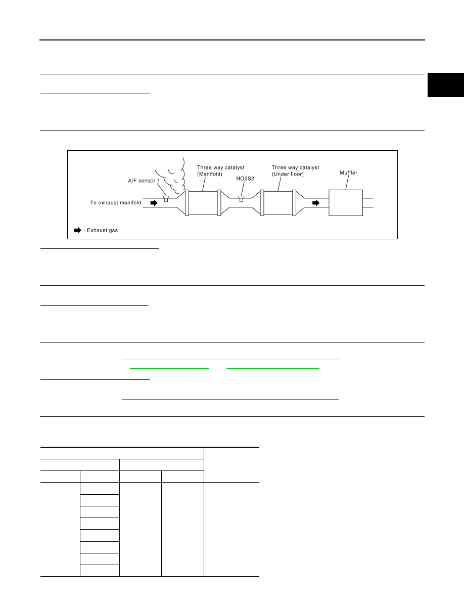
CHECK EXHAUST GAS LEAKAGE

1.

Start engine and run it at idle.

2.

Listen for an exhaust gas leakage before the three way catalyst (manifold).

Is exhaust gas leakage detected?

YES

>> Repair or replace malfunctioning part.

NO

>> GO TO 3.

3.

CHECK INTAKE AIR LEAKAGE

Listen for an intake air leakage after the mass air flow sensor.
Is intake air leakage detected?

YES

>> Repair or replace malfunctioning part.

NO

>> GO TO 4.

4.

CHECK IDLE SPEED AND IGNITION TIMING

Check idle speed and ignition timing.
For procedure, refer to 

EC-576, "BASIC INSPECTION : Special Repair Requirement"

.

For specification, refer to 

EC-1241, "Idle Speed"

 and 

EC-1241, "Ignition Timing"

.

Is the inspection result normal?

YES

>> GO TO 5.

NO

>> Follow the 

EC-576, "BASIC INSPECTION : Special Repair Requirement"

.

5.

CHECK FUEL INJECTORS

1.

Stop engine and then turn ignition switch ON.

2.

Check the voltage between ECM harness connector terminals as per the following.

PBIB1216E

ECM

Voltage

+

Connector

Terminal

Connector

Terminal

F110

17

M160

128

Battery voltage

21

25

29

33

37

41

45

EC-886

< DTC/CIRCUIT DIAGNOSIS >

[VK50VE]

P0420, P0430 THREE WAY CATALYST FUNCTION

Is the inspection result normal?

YES

>> GO TO 6.

NO

>> Perform 

EC-1103, "Diagnosis Procedure"

.

6.

CHECK FUNCTION OF IGNITION COIL-I

CAUTION:

Perform the following procedure in a place with no combustible objects and good ventilation.
1.

Turn ignition switch OFF.

2.

Remove fuel pump fuse (1) in IPDM E/R (2) to release fuel pres-
sure.
NOTE:
Do not use CONSULT-III to release fuel pressure, or fuel pres-
sure applies again during the following procedure.

3.

Start engine.

4.

After engine stalls, crank it 2 or 3 times to release all fuel pres-
sure.

5.

Turn ignition switch OFF.

6.

Remove all ignition coil harness connectors to avoid the electri-
cal discharge from the ignition coils.

7.

Remove ignition coil and spark plug of the cylinder to be
checked.

8.

Crank engine for 5 seconds or more to remove combustion gas in the cylinder.

9.

Connect spark plug and harness connector to ignition coil.

10. Fix ignition coil using a rope etc. with gap of 13 - 17 mm (0.52 -

0.66 in) between the edge of the spark plug and grounded metal
portion as shown in the figure.

11. Crank engine for approximately 3 seconds, and check whether

spark is generated between the spark plug and the grounded
metal portion.

CAUTION:

• Never place the spark plug and the ignition coil within 50

cm (19.7 in) each other. Be careful not to get an electrical
shock while checking, because the electrical discharge
voltage becomes 20 kV or more.

• It might damage the ignition coil if the gap of more than 17 mm (0.66 in) is made.
NOTE:
When the gap is less than 13 mm (0.52 in), a spark might be generated even if the coil is malfunc-
tioning.

Is the inspection result normal?

YES

>> GO TO 10.

NO

>> GO TO 7.

7.

CHECK FUNCTION OF IGNITION COIL-II

1.

Turn ignition switch OFF.

2.

Disconnect spark plug and connect a non-malfunctioning spark plug.

3.

Crank engine for approximately 3 seconds, and recheck whether spark is generated between the spark
plug and the grounded metal portion.

Is the inspection result normal?

YES

>> GO TO 8.

NO

>> Check ignition coil, power transistor and their circuits. Refer to 

EC-1114, "Diagnosis Procedure"

.

8.

CHECK SPARK PLUG

Spark should be generated.

JMBIA1552ZZ

JMBIA0066GB

Spark should be generated.

P0420, P0430 THREE WAY CATALYST FUNCTION

EC-887

< DTC/CIRCUIT DIAGNOSIS >

[VK50VE]

C

D

E

F

G

H

I

J

K

L

M

A

EC

N

P

O

Check the initial spark plug for fouling, etc.

Is the inspection result normal?

YES

>> Replace spark plug(s) with standard type one(s). For

spark plug type, refer to 

EM-282, "Spark Plug"

.

NO

>> Repair or clean spark plug. Then GO TO 9.

9.

CHECK FUNCTION OF IGNITION COIL-III

1.

Reconnect the initial spark plugs.

2.

Crank engine for approximately 3 seconds, and recheck whether spark is generated between the spark
plug and the grounded portion.

Is the inspection result normal?

YES

>> INSPECTION END

NO

>> Replace spark plug(s) with standard type one(s). For spark plug type, refer to 

EM-282, "Spark

Plug"

.

10.

CHECK FUEL INJECTOR

1.

Turn ignition switch OFF.

2.

Remove fuel injector assembly.
Refer to 

EM-182, "Removal and Installation"

.

Keep fuel hose and all fuel injectors connected to fuel tube.

3.

Disconnect all ignition coil harness connectors.

4.

Reconnect all fuel injector harness connectors disconnected.

5.

Turn ignition switch ON.

6.

Check that fuel does not drip from fuel injector.

Does fuel drip from fuel injector?

YES

>> Replace the fuel injector(s) from which fuel is dripping.

NO

>> GO TO 11.

11.

CHECK INTERMITTENT INCIDENT

Refer to 

GI-36, "Intermittent Incident"

.

Is the inspection result normal?

YES

>> Replace three way catalyst assembly.

NO

>> Repair or replace harness or connector. 

SEF156I

Spark should be generated.

EC-888

< DTC/CIRCUIT DIAGNOSIS >

[VK50VE]

P0441 EVAP CONTROL SYSTEM

P0441 EVAP CONTROL SYSTEM

DTC Logic

INFOID:0000000005237362

DTC DETECTION LOGIC

NOTE:
If DTC P0441 is displayed with other DTC such as P2122, P2123, P2127, P2128 or P2138, first perform
trouble diagnosis for other DTC.
In this evaporative emission (EVAP) control system, purge flow occurs during non-closed throttle conditions.
Purge volume is related to air intake volume. Under normal purge conditions (non-closed throttle), the EVAP
canister purge volume control solenoid valve is open to admit purge flow. Purge flow exposes the EVAP con-
trol system pressure sensor to intake manifold vacuum.
Under normal conditions (non-closed throttle), sensor output voltage indicates if pressure drop and purge flow
are adequate. If not, a malfunction is determined.

DTC CONFIRMATION PROCEDURE

1.

PRECONDITIONING

If DTC Confirmation Procedure has been previously conducted, always perform the following procedure
before conducting the next test. 
1.

Turn ignition switch OFF and wait at least 10 seconds.

2.

Turn ignition switch ON.

3.

Turn ignition switch OFF and wait at least 10 seconds.

Will CONSULT-III be used?

YES

>> GO TO 2.

NO

>> GO TO 5.

PBIB1026E

DTC No.

Trouble diagnosis name

DTC detecting condition

Possible cause

P0441

EVAP control system in-
correct purge flow

EVAP control system does not operate 
properly, EVAP control system has a leak 
between intake manifold and EVAP control 
system pressure sensor.

• EVAP canister purge volume control solenoid 

valve stuck closed

• EVAP control system pressure sensor and the 

circuit

• Loose, disconnected or improper connection of 

rubber tube

• Blocked rubber tube
• Cracked EVAP canister
• EVAP canister purge volume control solenoid 

valve circuit

• Accelerator pedal position sensor
• Blocked purge port
• EVAP canister vent control valve


Content   ..  834  835  836  837   ..