Infiniti FX35, FX50 (S51). Manual - part 568


  Index      Infiniti     Infiniti FX35, FX50 (S51) - service repair manual 2010 year


Search            


Content   ..  566  567  568  569   ..


Infiniti FX35, FX50 (S51). Manual - part 568


PREPARATION

DLN-107

< PREPARATION >

[FRONT PROPELLER SHAFT: 2S56A]

C

E

F

G

H

I

J

K

L

M

A

B

DLN

N

O

P

PREPARATION

PREPARATION

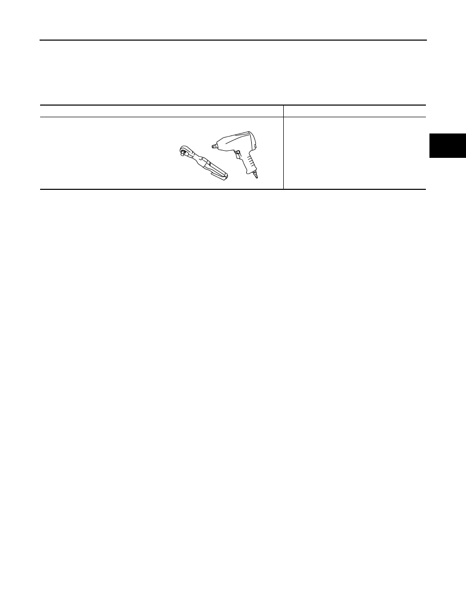
Commercial Service Tools

INFOID:0000000005249143

Tool name

Description

Power tool

Loosening bolts and nuts

PBIC0190E

DLN-108

< PERIODIC MAINTENANCE >

[FRONT PROPELLER SHAFT: 2S56A]

FRONT PROPELLER SHAFT

PERIODIC MAINTENANCE

FRONT PROPELLER SHAFT

Inspection

INFOID:0000000005249144

NOISE

Check the propeller shaft tube surface for dents or cracks. If damaged, replace propeller shaft assembly.

VIBRATION

If vibration is present at high speed, inspect propeller shaft runout
first.
1.

With a dial indicator, measure propeller shaft runout at runout
measuring points by rotating final drive companion flange with
hands.

2.

If runout still exceeds specifications, separate propeller shaft at
final drive companion flange; then rotate companion flange 90,
180, 270 degrees and install propeller shaft.

3.

Check runout again. If runout still exceeds specifications, replace propeller shaft assembly. 

4.

Check the vibration by driving vehicle.

RUNOUT MEASURING POINT

Propeller shaft runout measuring point (Point “ ”).

Limit

Propeller shaft runout

: Refer to 

DLN-114, "Pro-

peller Shaft Runout"

.

JPDID0185ZZ

Standard

A

: 381.5 mm (15.02 in) 
(VQ35HR)

: 386.5 mm (15.22 in) 
(VK50VE)

PDIA0768J

FRONT PROPELLER SHAFT

DLN-109

< REMOVAL AND INSTALLATION >

[FRONT PROPELLER SHAFT: 2S56A]

C

E

F

G

H

I

J

K

L

M

A

B

DLN

N

O

P

REMOVAL AND INSTALLATION

FRONT PROPELLER SHAFT

VQ35HR

VQ35HR : Exploded View

INFOID:0000000005249145

VQ35HR : Removal and Installation

INFOID:0000000005249146

REMOVAL

1.

Shift the transaxle to the neutral position, and then release the parking brake.

2.

Remove engine undercover with a power tool.

3.

Remove exhaust front tube and three-way catalyst (bank 1) with a power tool. Refer to 

EX-5, "Exploded

View"

.

4.

Put matching mark on propeller shaft flange yoke and final drive
companion flange.

CAUTION:

For matching mark, use paint. Never damage propeller shaft
flange and final drive companion flange. 

5.

Remove the propeller shaft assembly fixing bolts.

6.

Move steering hydraulic line not to interfere with work. Refer to

ST-48, "VQ35HR : Exploded View"

.

CAUTION:

Wrap power steering piping interference area with shop
cloth or equivalent to protect power steering piping from
breakage.

7.

Support transfer assembly with a jack, remove rear engine mounting member. Refer to 

EM-87, "AWD :

Exploded View"

.

1.

O-ring

2.

Propeller shaft assembly

3.

Heat bracket

: Apply multi-purpose grease.

: Vehicle front

Refer to 

GI-4, "Components"

 for symbols not described above.

JPDID0273GB

SDIA1517E

DLN-110

< REMOVAL AND INSTALLATION >

[FRONT PROPELLER SHAFT: 2S56A]

FRONT PROPELLER SHAFT

8.

Remove propeller shaft assembly from the front final drive and
transfer.

CAUTION:

• Never damage the transfer front oil seal.
• Wrap transmission interference area (A) with shop cloth

or equivalent to protect propeller shaft from breakage.

9.

Remove propeller shaft assembly from O-ring.

10. Remove heat bracket.

INSTALLATION

Note the following, and install in the reverse order of removal.
• Align matching mark to install propeller shaft assembly to final

drive companion flange.

• After assembly, perform a driving test to check propeller shaft

vibration. If vibration occurred, separate propeller shaft from final
drive. Reinstall companion flange after rotating it by 90, 180, 270
degrees. Then perform driving test and check propeller shaft vibra-
tion again at each point.

CAUTION:

• Never damage the transfer front oil seal.
• Wrap power steering piping interference area with shop cloth

or equivalent to protect power steering piping from breakage.

• Wrap transmission interference area (A) with shop cloth or

equivalent to protect propeller shaft from breakage.

• Never reuse O-ring.
• Apply multi-purpose grease onto O-ring.

VQ35HR : Inspection

INFOID:0000000005249147

APPEARANCE

Check propeller shaft for bend and damage. If damage is detected, replace propeller shaft assembly.

PROPELLER SHAFT RUNOUT

Check propeller shaft runout at measuring point with a dial indicator.
If runout exceeds specifications, replace propeller shaft assembly.
For measuring point, refer to 

DLN-108, "Inspection"

.

JOURNAL AXIAL PLAY

: Vehicle front

JSDIA0849ZZ

SDIA1517E

JSDIA0849ZZ

Limit

Propeller shaft runout

: Refer to 

DLN-114, "Pro-

peller Shaft Runout"

.

JSDIA0083ZZ


Content   ..  566  567  568  569   ..