Infiniti FX35, FX50 (S51). Manual - part 436


  Index      Infiniti     Infiniti FX35, FX50 (S51) - service repair manual 2010 year


Search            


Content   ..  434  435  436  437   ..


Infiniti FX35, FX50 (S51). Manual - part 436


CHG

PREPARATION

CHG-25

< PREPARATION >

C

D

E

F

G

H

I

J

K

L

B

A

O

P

N

PREPARATION

PREPARATION

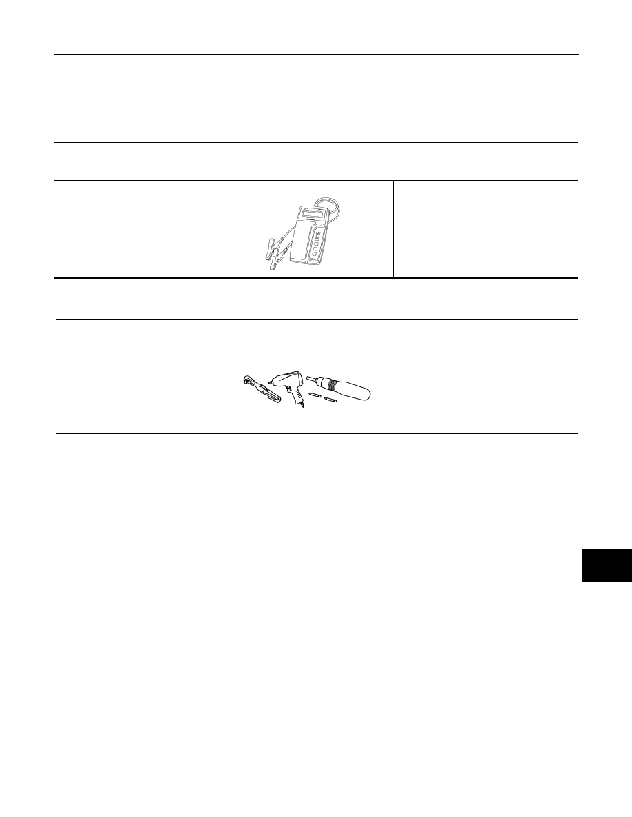
Special Service Tools

INFOID:0000000005242976

Commercial Service Tools

INFOID:0000000005242977

Tool number

(Kent-Moore No.)

Tool name

Description

(J-44373 Model MCR620)
Starting/Charging System Tester

Tests starting and charging systems.
For operating instructions, refer to Technical 
Service Bulletin.

SEL403X

Tool name

Description

Power tool

Loosening bolts, nuts and screws

PIIB1407E

CHG-26

< PERIODIC MAINTENANCE >

CHARGING SYSTEM PRELIMINARY INSPECTION

PERIODIC MAINTENANCE

CHARGING SYSTEM PRELIMINARY INSPECTION

Inspection Procedure

INFOID:0000000005242978

1.

CHECK BATTERY TERMINALS CONNECTION

Check if battery terminals are clean and tight.

Is the inspection result normal?

YES

>> GO TO 2.

NO

>> Repair battery terminals connection.

2.

CHECK FUSE

Check for blown fuse and fusible link.

Is the inspection result normal?

YES

>> GO TO 3.

NO

>> Be sure to eliminate the cause of malfunction before installing new fuse.

3.

CHECK “E” TERMINAL CONNECTION

Check if “E” terminal (alternator ground harness) is clean and tight.
Is the inspection result normal?

YES

>> GO TO 4.

NO

>> Repair “E” terminal connection.

4.

CHECK DRIVE BELT TENSION

Check drive belt tension. 
• VQ35HR  

EM-15, "Checking"

.

• VK50VE  

EM-163, "Checking"

.

Is the inspection result normal?

YES

>> INSPECTION END

NO

>> Repair as needed.

Unit

Power source (Power supply terminals)

Fuse No.

Alternator

Battery (“S” terminal)

31

Combination meter

Ignition switch ON (“L” terminal)

4

CHG

POWER GENERATION VOLTAGE VARIABLE CONTROL SYSTEM OPERATION 

INSPECTION

CHG-27

< PERIODIC MAINTENANCE >

C

D

E

F

G

H

I

J

K

L

B

A

O

P

N

POWER GENERATION VOLTAGE VARIABLE CONTROL SYSTEM OPER-
ATION INSPECTION

Inspection Procedure

INFOID:0000000005242979

CAUTION:

When performing this inspection, always use a charged battery that has completed the battery inspec-
tion. (When the charging rate of the battery is low, the response speed of the voltage change will
become slow. This can cause an incorrect inspection.)

1.

CHECK ECM (CONSULT-III)

Perform ECM self-diagnosis with CONSULT-III. Refer to the following.
• VQ35HR models: 

EC-124, "CONSULT-III Function"

.

• VK50VE models: 

EC-718, "CONSULT-III Function"

.

Self-diagnostic results content

No malfunction detected>> GO TO 2.
Malfunction detected>> Check applicable parts, and repair or replace corresponding parts.

2.

CHECK OPERATION OF POWER GENERATION VOLTAGE VARIABLE CONTROL SYSTEM

1.

Connect CONSULT-III and start the engine.

2.

The selector lever is in “P” or “N” position and all of the electric loads and A/C, etc. are turned OFF.

3.

Select “ALTERNATOR DUTY” at “Active Test” of “ENGINE”, and then check the value of “BATTERY
VOLT” monitor when DUTY value of “ALTERNATOR DUTY” is set to 40.0 %.

4.

Check the value of “BATTERY VOLT” monitor when DUTY value of “ALTERNATOR DUTY” is set to
80.0%.

Is the measurement value within the specification?

YES

>> INSPECTION END

NO

>> GO TO 3.

3.

CHECK IPDM E/R (CONSULT-III)

Perform IPDM E/R self-diagnosis with CONSULT-III. Refer to the following.
• VQ35HR models: 

PCS-13, "CONSULT-III Function (IPDM E/R)"

.

• VK50VE models: 

PCS-13, "CONSULT-III Function (IPDM E/R)"

.

Self-diagnostic results content

No malfunction detected>> GO TO 4.
Malfunction detected>> Check applicable parts, and repair or replace corresponding parts.

4.

CHECK HARNESS BETWEEN ALTERNATOR AND IPDM E/R

1.

Turn ignition switch OFF.

2.

Disconnect alternator connector and IPDM E/R connector.

3.

Check continuity between alternator harness connector and IPDM E/R harness connector.

“BATTERY VOLT”

2 seconds after setting the 
DUTY value of “ALTERNA-
TOR DUTY” to 40.0 %

: 12 - 13.6 V

“BATTERY VOLT”

20 seconds after setting 
the DUTY value of “ALTER-
NATOR DUTY” to 80.0 %

: +0.5 V or more against 
the value of “BATTERY 
VOLT” monitor when 
DUTY value is 40.0 %

CHG-28

< PERIODIC MAINTENANCE >

POWER GENERATION VOLTAGE VARIABLE CONTROL SYSTEM OPERATION 

INSPECTION

4.

Check continuity between alternator harness connector and ground.

Is the inspection result normal?

YES

>> Replace IPDM E/R.

NO

>> Repair harness or connector between IPDM E/R and alternator. 

Alternator harness connector

IPDM E/R harness connector

Continuity

Connector

Terminal

Connector

Terminal

F36

4

 E7

76

Existed

Alternator harness connector

Ground

Continuity

Connector

Terminal

F36

4

Not existed


Content   ..  434  435  436  437   ..