Infiniti FX35, FX50 (S51). Manual - part 366
CCS-284
< DTC/CIRCUIT DIAGNOSIS >
[DCA]
C1A40 SYSTEM SWITCH CIRCUIT
2.
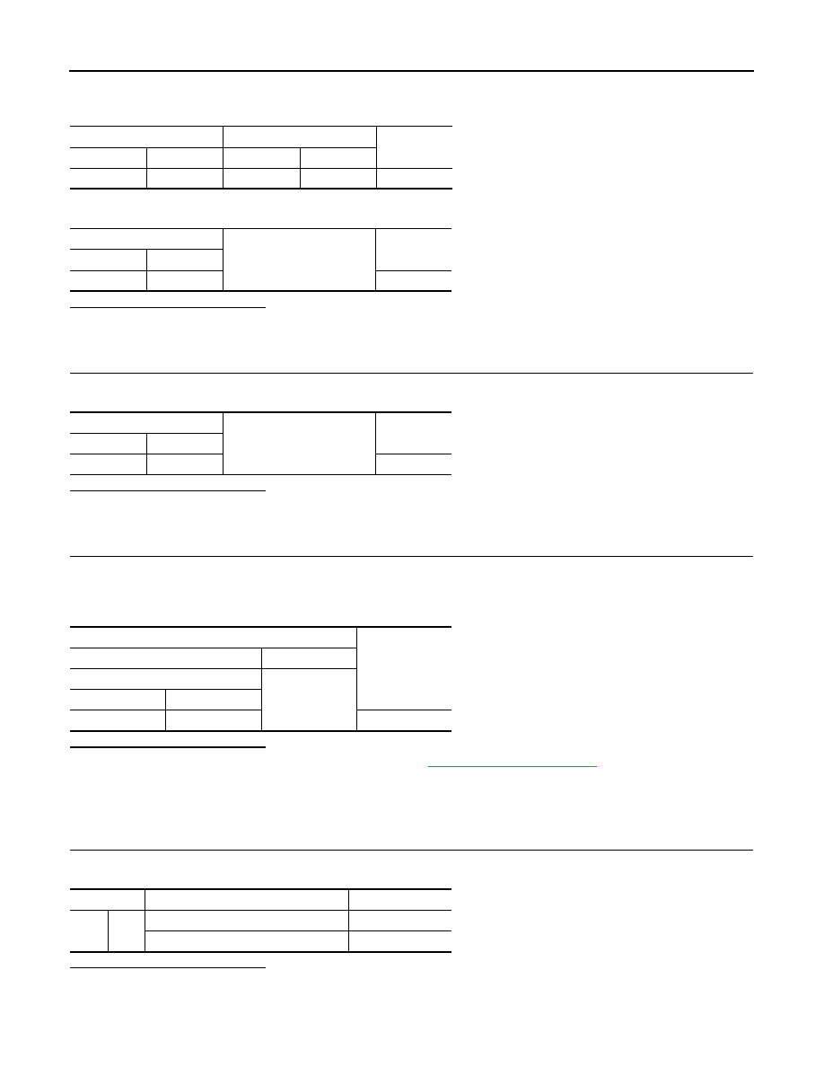
Check for continuity between the brake booster control unit harness connector and IBA OFF switch har-
ness connector.
3.
Check for continuity between brake booster control unit and ground.
Is the inspection result normal?
YES
>> GO TO 5.
NO
>> Repair the harnesses or connectors.
5.
CHECK IBA OFF SWITCH GROUND CIRCUIT
Check for continuity between IBA OFF switch harness connector and ground.
Is the inspection result normal?
YES
>> GO TO 6.
NO
>> Repair the harnesses or connectors.
6.
CHECK IBA OFF SWITCH SIGNAL
1.
Connect the brake booster control unit connector.
2.
Turn the ignition switch ON.
3.
Check voltage between brake booster control unit harness connector and ground.
Is the inspection result normal?
YES
>> Replace ICC sensor integrated unit. Refer to
NO
>> Replace the brake booster control unit.
Component Inspection (IBA OFF Switch)
INFOID:0000000005501911
1.
CHECK IBA OFF SWITCH
Check for continuity of IBA OFF switch.
Is the inspection result normal?
YES
>> INSPECTION END
NO
>> Replace the IBA OFF switch.
Brake booster control unit
IBA OFF switch
Continuity
Connector
Terminal
Connector
Terminal
B249
40
M184
7
Existed
Brake booster control unit
Ground
Continuity
Connector
Terminal
B249
40
Not existed
IBA OFF switch
Ground
Continuity
Connector
Terminal
M184
6
Existed
Terminals
Voltage
(Approx.)
(+)
(–)
Brake booster control unit
Ground
Connector
Terminal
B249
40
Battery voltage
Terminal
Condition
Continuity
6
7
When the IBA OFF switch is pressed
Existed
When the IBA OFF switch is released
Not existed