Content .. 1647 1648 1649 1650 ..
Infiniti FX35, FX50 (S51). Manual - part 1649
INTELLIGENT KEY SYSTEM/ENGINE START FUNCTION
SEC-9
< SYSTEM DESCRIPTION >
[INTELLIGENT KEY SYSTEM]
C
D
E
F
G
H
I
J
L
M
A
B
SEC
N
O
P
SYSTEM DESCRIPTION
INTELLIGENT KEY SYSTEM/ENGINE START FUNCTION
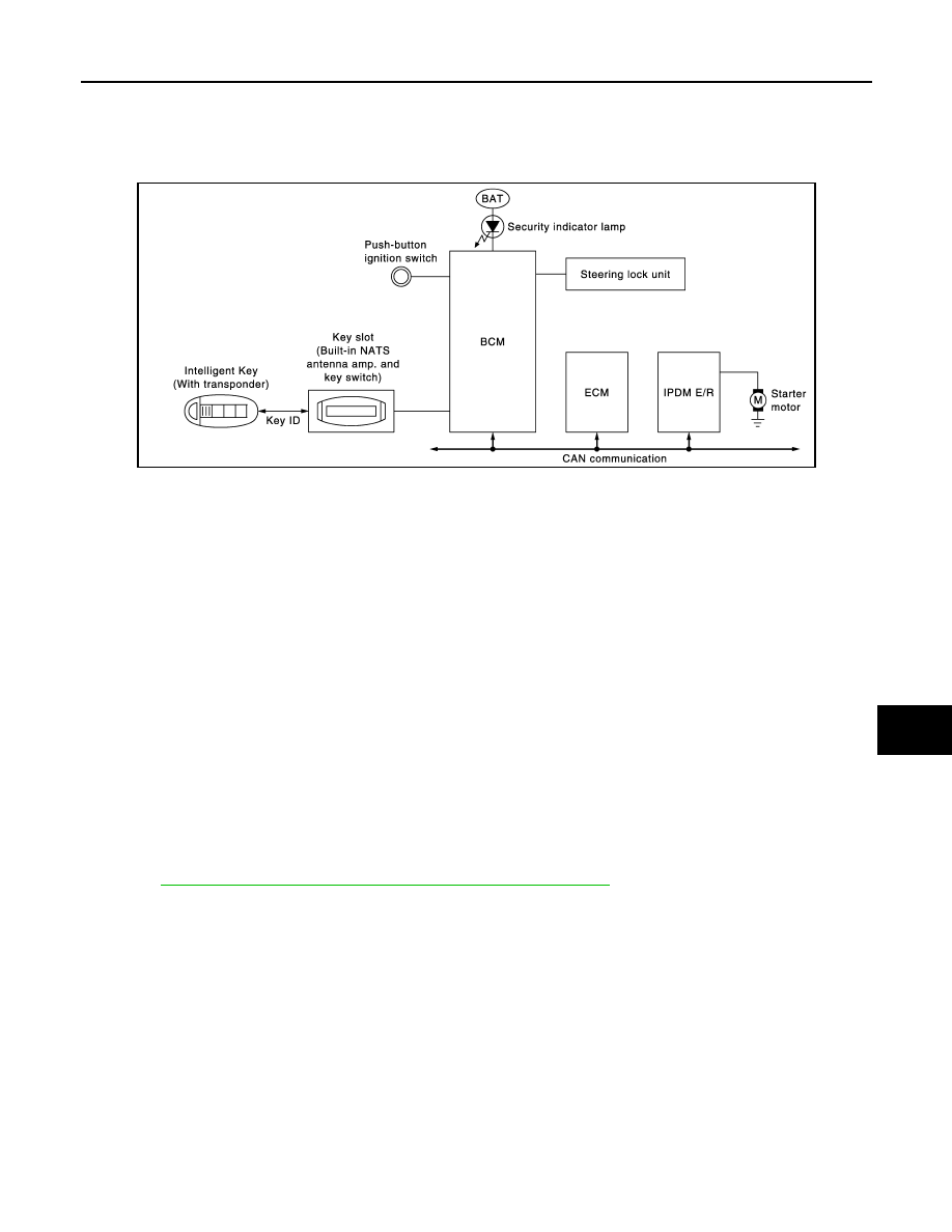
System Diagram
INFOID:0000000005249398
System Description
INFOID:0000000005249399
• The engine start function of Intelligent Key system is a system that makes it possible to start and stop the
engine without removing the key. It verifies the electronic ID using two-way communication when pressing
the push-button ignition switch while carrying the Intelligent Key, which operates based on the results of
electronic ID verification for Intelligent Key using two-way communication between the Intelligent Key and
the vehicle.
NOTE:
The driver should carry the Intelligent Key at all times.
• Intelligent Key has 2 IDs [for Intelligent Key and for IVIS (NATS)]. It can perform the door lock/unlock opera-
tion and the push-button ignition switch operation when the registered Intelligent Key is carried.
• When the Intelligent Key battery is discharged, it can be used as emergency back-up by inserting the Intelli-
gent Key in the key slot. At that time, perform the IVIS (NATS) ID verification. If it is used when the Intelligent
Key is carried, perform the Intelligent Key ID verification.
• If the ID is successfully verified, and when push-button ignition switch is pressed, steering lock will be
released and initiating the engine will be possible.
• If the door lock/unlock operation is performed when the Intelligent Key battery is discharged, all doors lock/
unlock can be performed by operating the driver door key cylinder using the mechanical key set in the Intel-
ligent Key.
• Up to 4 Intelligent Keys can be registered (Including the standard Intelligent Key) on request from the owner.
NOTE:
Refer to
DLK-16, "INTELLIGENT KEY SYSTEM : System Description"
for any functions other than engine
start function of Intelligent Key system.
PRECAUTIONS FOR INTELLIGENT KEY SYSTEM
• In the Intelligent Key system, the transponder [the chip for IVIS (NATS) ID verification] is integrated
into the Intelligent Key. (For the conventional models, it is integrated into the mechanical key.) There-
fore, the mechanical key cannot perform the ID verification, and thus it cannot start the engine.
Instead, the IVIS (NATS) ID verification can be performed by inserting the Intelligent Key into the key
slot, and then it can start the engine.
OPERATION WHEN INTELLIGENT KEY IS CARRIED
1.
When the push-button ignition switch is pressed, the BCM signals the inside key antenna and transmits
the request signal to the Intelligent Key.
2.
The Intelligent Key receives the request signal and transmits the Intelligent Key ID signal to the BCM via
the remote keyless entry receiver.
3.
The Intelligent Key receives the Intelligent Key ID signal and verifies it with the registered ID.
JMKIA2503GB