Infiniti FX35, FX50 (S51). Manual - part 1204


  Index      Infiniti     Infiniti FX35, FX50 (S51) - service repair manual 2010 year


Search            


Content   ..  1202  1203  1204  1205   ..


Infiniti FX35, FX50 (S51). Manual - part 1204


INL-16

< SYSTEM DESCRIPTION >

ILLUMINATION CONTROL SYSTEM

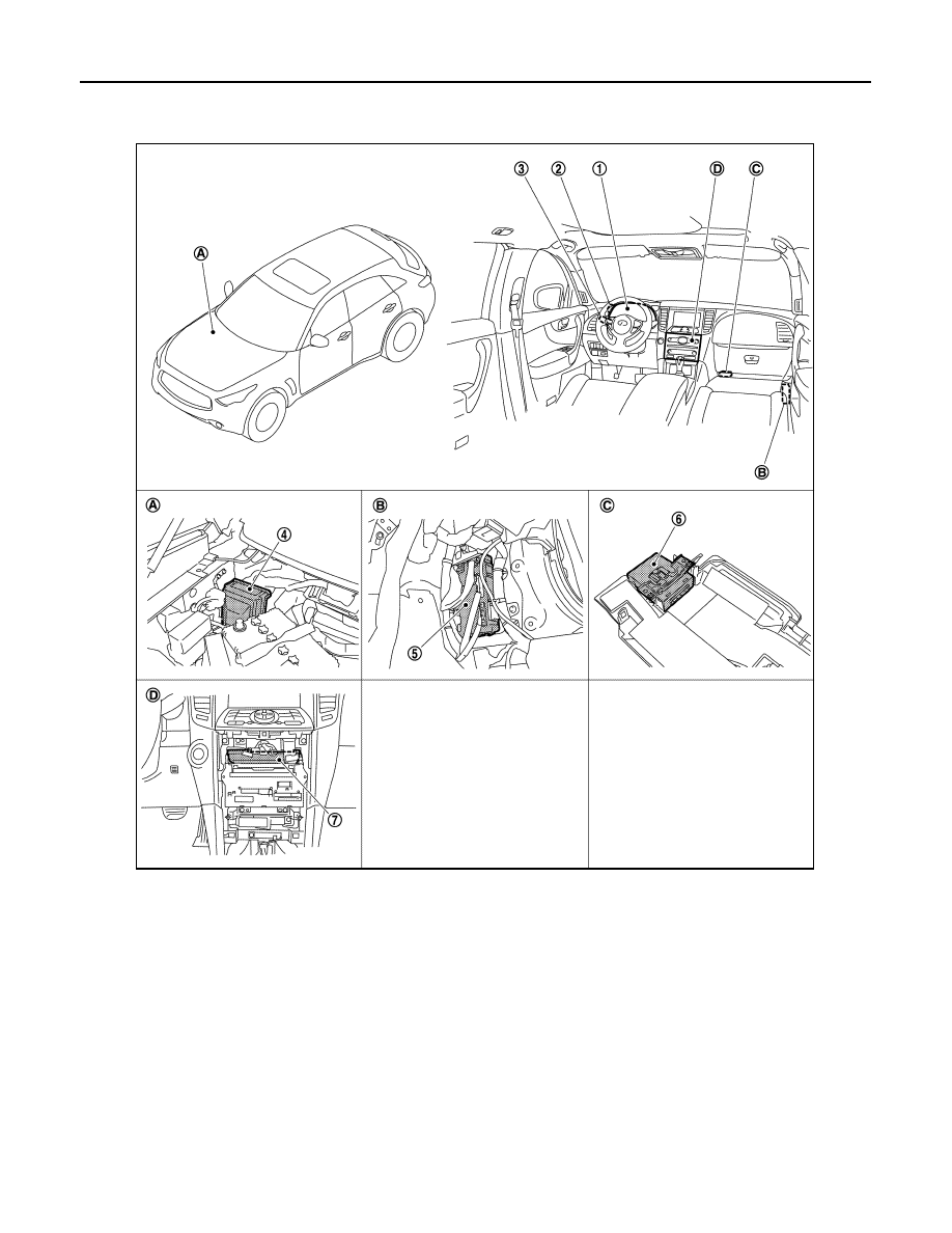
Component Parts Location

INFOID:0000000005245553

1.

Combination meter

2.

Illumination control switch

3.

Combination switch

4.

IPDM E/R

5.

BCM

6.

Total illumination control unit

7.

Unified meter and A/C amp.

A.

Engine room dash panel (RH)

B.

Dash side lower (passenger side)

C.

Instrument lower cover LH

D.

Behind the cluster lid C

JPLIA1250ZZ

ILLUMINATION CONTROL SYSTEM

INL-17

< SYSTEM DESCRIPTION >

C

D

E

F

G

H

I

J

K

M

A

B

INL

N

O

P

Component Description

INFOID:0000000005245554

Part

Description

BCM

• Detects each switch condition by the combination switch reading function.
• Judges the illumination lamp ON/OFF status depending on the vehicle condition. 

And then it transmits position light request signal to IPDM E/R and combination 
meter via CAN communication (through the unified meter and A/C amp.). 

IPDM E/R

Controls the integrated relay according to the request from BCM via CAN communica-
tion.

Combination meter

• Enters in the nighttime mode according to the request from BCM via CAN commu-

nication.

• Controls each illumination brightness in the nighttime mode.

Refer to 

MWI-27, "METER ILLUMINATION CONTROL : System Diagram"

.

Total illumination control unit

• Turns each illumination (linked with hospitality lighting system) ON according to tail 

lamp signal from IPDM E/R

• Controls each illumination (linked with hospitality lighting system) brightness accord-

ing to the illumination control signal from combination meter.

Combination switch
(Lighting & turn signal switch)

Refer to 

BCS-8, "System Diagram"

.

INL-18

< SYSTEM DESCRIPTION >

DIAGNOSIS SYSTEM (TOTAL ILLUMINATION CONTROL UNIT)

DIAGNOSIS SYSTEM (TOTAL ILLUMINATION CONTROL UNIT)

CONSULT-III Function (TOTAL ILLUM C/U)

INFOID:0000000005245555

APPLICATION ITEM

CONSULT-III performs the following functions via DDL2 communication line with the total illumination control
unit.

WORK SUPPORT

*: Factory setting

DATA MONITOR

Diagnosis mode

Function Description

Work Support

Changes the setting for each function.

Data Monitor

Total illumination control unit input/output signals are displayed.

Active Test

The signals used to activate each device are forcibly supplied from total illumination control unit.

Ecu Identification

Total illumination control unit part number is displayed.

JPLIA1209GB

Service item

Setting item

Setting

FOOT LAMP FADE-IN/OUT

FADE-IN

0 – 3.0 sec. (1.0 sec.*)

Sets fade-in/fade-out time of the foot lamps.

FADE-OUT

0 – 3.0 sec. (1.0 sec.*)

MAP&PERSNL LAMP FADE-IN/OUT

FADE-IN

0 – 3.0 sec. (1.0 sec.*)

Sets fade-in/fade-out time of the map lamps and per-
sonal lamps.

FADE-OUT

0 – 3.0 sec. (1.0 sec.*)

PUDDLE LAMP FADE-IN/OUT

FADE-IN

0 – 3.0 sec. (0 sec.*)

Sets fade-in/fade-out time of the puddle lamps.

FADE-OUT

0 – 3.0 sec. (3.0 sec.*)

MOOD LAMP FADE-IN/OUT

FADE-IN

0 – 3.0 sec. (1.0 sec.*)

Sets fade-in/fade-out time of the mood lamps.

FADE-OUT

0 – 3.0 sec. (1.0 sec.*)

AMBIENCE LAMP FADE-IN/OUT

FADE-IN

0 – 3.0 sec. (1.0 sec.*)

Sets fade-in/fade-out time of the ambience lamp 
(center console indirect illumination).

FADE-OUT

0 – 3.0 sec. (1.0 sec.*)

HSPL ILLUMINATION FADE-IN/OUT

FADE-IN

0 – 3.0 sec. (1.0 sec.*)

Sets fade-in/fade-out time of each illumination (linked 
with hospitality lighting).

FADE-OUT

0 – 3.0 sec. (1.0 sec.*)

E/G SW ILLUMI FADE-IN/OUT

FADE-IN

0 – 3.0 sec. (1.5 sec.*)

Sets fade-in/fade-out time of the engine switch illumi-
nation.

FADE-OUT

0 – 3.0 sec. (1.5 sec.*)

E/G SW ILL HEART BEAT FUNCTION 

On*

With the engine switch illumination heart beat func-
tion

Off

Without the engine switch illumination heart beat 
function

DIAGNOSIS SYSTEM (TOTAL ILLUMINATION CONTROL UNIT)

INL-19

< SYSTEM DESCRIPTION >

C

D

E

F

G

H

I

J

K

M

A

B

INL

N

O

P

ACTIVE TEST

Monitor item

[Unit]

Description

BAT SAVER SIGNAL
[On/Off]

Battery saver status input from BCM

IGN SIGNAL
[On/Off]

Ignition switch ON signal status

ACC SIGNAL
[On/Off]

Ignition switch ACC signal status

ROOM LAMP REQ
[On/Off]

Room lamp timer signal status input from BCM

TAIL LAMP SIGNAL
[On/Off]

Tail lamp status input from IPDM E/R

DOOR SW-DR
[On/Off]

The switch status input from front door switch (driver side)

DOOR SW-AS
[On/Off]

The switch status input from front door switch (passenger side)

DOOR SW-RR
[On/Off]

The switch status input from rear door switch (RH)

DOOR SW- RL
[On/Off]

The switch status input from rear door switch (LH)

MAP LAMP SW
[Door/All On/Off]

The switch status input from map lamp main switch

ENGINE SW ILLUMI
[STEADY/PULSE/Off]

Control status of the engine switch illumination

FOOT LAMP
[%]

Brightening rate of the foot lamps

MAP LAMP-DR
[%]

Brightening rate of the map lamp (driver side)

MAP LAMP-AS
[%]

Brightening rate of the map lamp (passenger side)

PERSONAL LMP-RR
[%]

Brightening rate of the personal lamp (RH)

PERSONAL LMP-RL
[%]

Brightening rate of the personal lamp (LH)

PUDDLE LAMP
[%]

Brightening rate of the puddle lamps

MOOD LAMP
[%]

Brightening rate of the mood lamps

AMBIENCE LAMP
[%]

Brightening rate of the ambience lamp (center console indirect illumination)

HSPL ILLUMI
[%]

Brightening rate of each illumination (linked with hospitality lighting)

ILLUM CONT SIGNAL
[%]

Illumination control signal status input from combination meter

Test item

Operation

Description

ENGINE SWITCH ILLUMI-
NATION

On

Total illumination control unit turns ON/OFF the engine switch illumination.

Off

FOOT LAMP

On

Total illumination control unit turns ON/OFF the foot lamps.

Off


Content   ..  1202  1203  1204  1205   ..