Content .. 1080 1081 1082 1083 ..
Infiniti FX35, FX50 (S51). Manual - part 1082
FAX-26
< REMOVAL AND INSTALLATION >
[AWD]
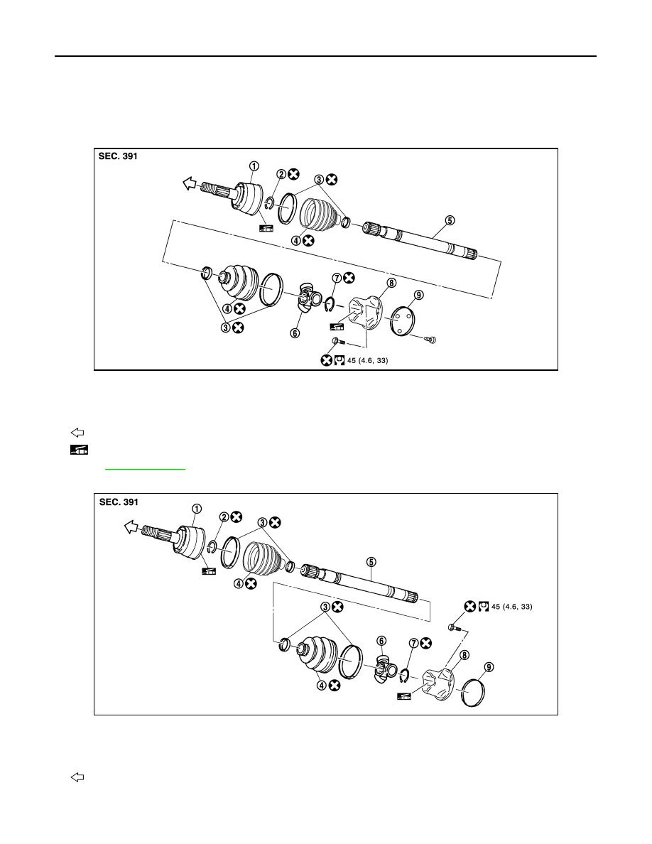
FRONT DRIVE SHAFT
FRONT DRIVE SHAFT
Exploded View
INFOID:0000000005248994
LEFT SIDE
VQ35HR
VK50VE
JPDIF0168GB
1.
Joint sub-assembly
2.
Circular clip
3.
Boot band
4.
Boot
5.
Shaft
6.
Spider assembly
7.
Snap ring
8.
Housing
9.
Plug
: Wheel side
: NISSAN genuine grease or an equivalent.
Refer to
for symbols not described on the above.
JPDIF0191GB
1.
Joint sub-assembly
2.
Circular clip
3.
Boot band
4.
Boot
5.
Shaft
6.
Spider assembly
7.
Snap ring
8.
Housing
9.
Plug
: Wheel side