Infiniti FX35, FX50 (S51). Manual - part 10


  Index      Infiniti     Infiniti FX35, FX50 (S51) - service repair manual 2010 year


Search            


Content   ..  8  9  10  11   ..


Infiniti FX35, FX50 (S51). Manual - part 10


ADP-32

< SYSTEM DESCRIPTION >

AUTOMATIC DRIVE POSITIONER SYSTEM

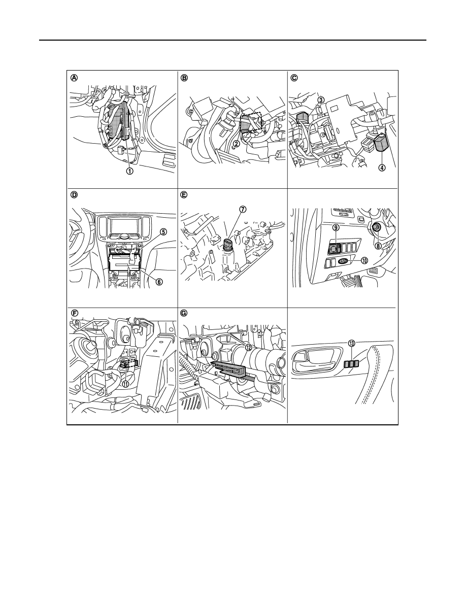
EXIT ASSIST FUNCTION : Component Parts Location

INFOID:0000000005249641

1.

BCM M118, M119, M122, M123

2.

Automatic drive positioner control unit 
M51, M52

3.

Tilt motor M49

4.

Telescopic motor M49

5.

Unified meter and A/C amp. M67

6.

AV control unit
With NAVI M87, M88
Without NAVI M83, M85

7.

AT assembly connector F51

8.

Tilt & telescopic switch M31

9.

Door mirror remote control switch 
M26

10. Key slot M22

11.

Tilt sensor M48

12. Telescopic sensor M48

13. Seat memory switch D5

A.

Dash side lower (Passenger side)

B.

View with instrument driver lower 
panel removed

C.

View with steering column cover low-
er and upper removed

D.

Behind cluster lid C

E.

A/T assembly
(TCM is built in A/T assembly)

F.

View with instrument driver lower 
panel removed

G

View with steering column cover low-
er and upper removed

JMJIA1961ZZ

AUTOMATIC DRIVE POSITIONER SYSTEM

ADP-33

< SYSTEM DESCRIPTION >

C

D

E

F

G

H

I

K

L

M

A

B

ADP

N

O

P

EXIT ASSIST FUNCTION : Component Description

INFOID:0000000005249642

CONTROL UNITS

INPUT PARTS

Switches

Sensors

OUTPUT PARTS

14. Front door switch (driver side) B16

15. A/T shift selector (detention switch) 

M137

16. Sliding, lifting switch

 (Power seat switch B459)

17. Reclining switch (power seat switch 

B459)

18.  Door mirror (driver side) D3

19. Reclining motor B454

20.  Driver seat control unit B451, B452

21. Lifting motor (front) B455

22. Lifting motor (rear) B456

23. Sliding motor B461

24. Sliding sensor B453

H.

View with center console assembly 
removed

I.

View with seat cushion pad and seat-
back pad removed

J.

Backside of the seat cushion

JMJIA1962ZZ

Item

Function

Driver seat control unit

• Operates the seat sliding motor for a constant amount.
• Requests the operations of tilt motor and telescopic motor to automatic drive po-

sitioner control unit.

Automatic drive positioner control unit

Operates the tilt motor and telescopic motor with the request from the driver seat 
control.

BCM

Recognizes the following status and transmits it to the driver seat control unit via 
CAN communication.
• Driver door: OPEN/CLOSE

Item

Function

Front door switch (driver side)

Detect front door (driver side) open/close status. 

Item

Function

Tilt and telescopic sensor

Detect the up/down and front/rear position of steering column.

Sliding sensor

Detect the front/rear position of seat.

ADP-34

< SYSTEM DESCRIPTION >

AUTOMATIC DRIVE POSITIONER SYSTEM

ENTRY ASSIST FUNCTION

ENTRY ASSIST FUNCTION : System Diagram

INFOID:0000000005249643

ENTRY ASSIST FUNCTION : System Description

INFOID:0000000005249644

OUTLINE

The seat is in the exiting position when either following condition (A or B) is satisfied, the seat returns from
exiting position to the previous driving position.
NOTE:
• This function is set to ON before delivery (initial setting).
• Further information for the system setting procedure. Refer to 

ADP-11, "SYSTEM SETTING : Description"

.

OPERATION PROCEDURE

1.

A: Turn the ignition switch ON.
B: Turn the ignition switch from OFF to ACC after closing the driver door.

2.

Driver seat and steering column will return from the exiting position to entry position.

OPERATION CONDITION

Satisfy all of the following items. The entry assist function is not performed if these items are not satisfied.

Item

Function

Tilt and telescopic motor

Move the steering column upward/downward and forward/backward.

Sliding motor

Slide the seat forward/backward.

JMJIA0116GB

AUTOMATIC DRIVE POSITIONER SYSTEM

ADP-35

< SYSTEM DESCRIPTION >

C

D

E

F

G

H

I

K

L

M

A

B

ADP

N

O

P

DETAIL FLOW

Item

Request status

Seat, steering column

The vehicle is not moved after performing the 

exit assist function.

Switch inputs
• Power seat switch
• Tilt & telescopic switch
• Door mirror remote control switch
• Set switch
• Memory switch

OFF

(Not operated)

A/T selector lever

P position

Order

Input

Output

Control unit condition

1

Door switch/Ignition 
switch

Driver seat control unit receives the signals of [ignition switch signal] 
and [driver side door switch] from BCM via CAN communication.

2

Motors
(Sliding, tilt, tele-
scopic)

Driver side control unit operates the sliding motor when the operating 
conditions are satisfied and requests the operations of tilt motor and 
telescopic motor to automatic drive positioner control unit via UART 
communication. The automatic drive positioner control unit operates 
each motor.

Sensors
(Sliding, tilt, telescop-
ic)

Each sensor monitors the operating positions of seat and steering, 
and then stops the operation of each motor when each part reaches 
the recorded address.


Content   ..  8  9  10  11   ..