Infiniti EX35. Manual - part 947
STEP LAMP CIRCUIT
INL-25
< COMPONENT DIAGNOSIS >
C
D
E
F
G
H
I
J
K
M
A
B
INL
N
O
P
Does continuity exist?
YES
>> Replace step lamp.
NO
>> Repair harnesses or connectors.
3.
CHECK STEP LAMP SHORT CIRCUIT
1.
Turn ignition switch OFF.
2.
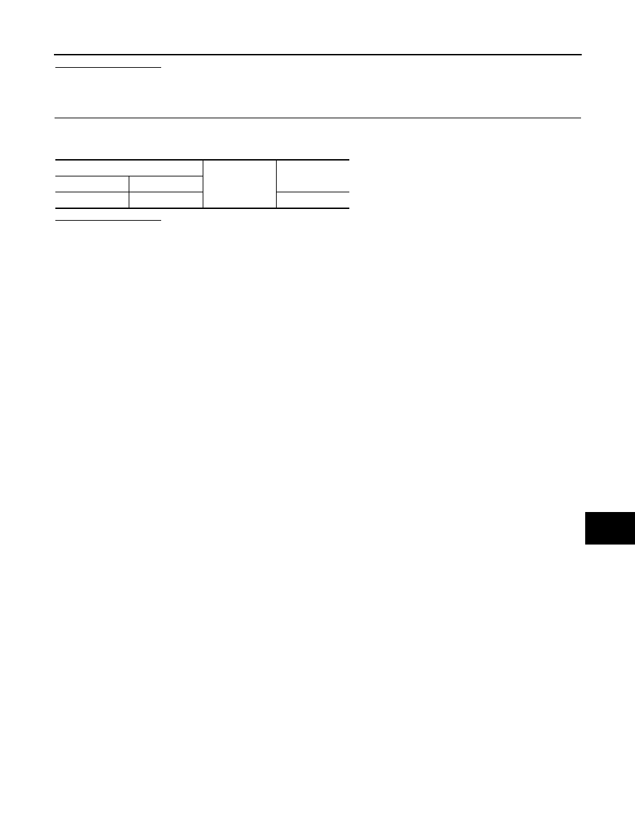
Check continuity between BCM harness connector and ground.
Does continuity exist?
YES
>> Repair the harnesses or connectors.
NO
>> Replace BCM.
BCM
Ground
Continuity
Connector
Terminal
M119
7
Not existed