Infiniti EX35. Manual - part 603


  Index      Infiniti     Infiniti EX35 - service repair manual 2008 year


Search            


Content   ..  601  602  603  604   ..


Infiniti EX35. Manual - part 603


EC-154

< COMPONENT DIAGNOSIS >

[VQ35HR]

P0078, P0084 EVT CONTROL MAGNET RETARDER

P0078, P0084 EVT CONTROL MAGNET RETARDER

Description

INFOID:0000000003133315

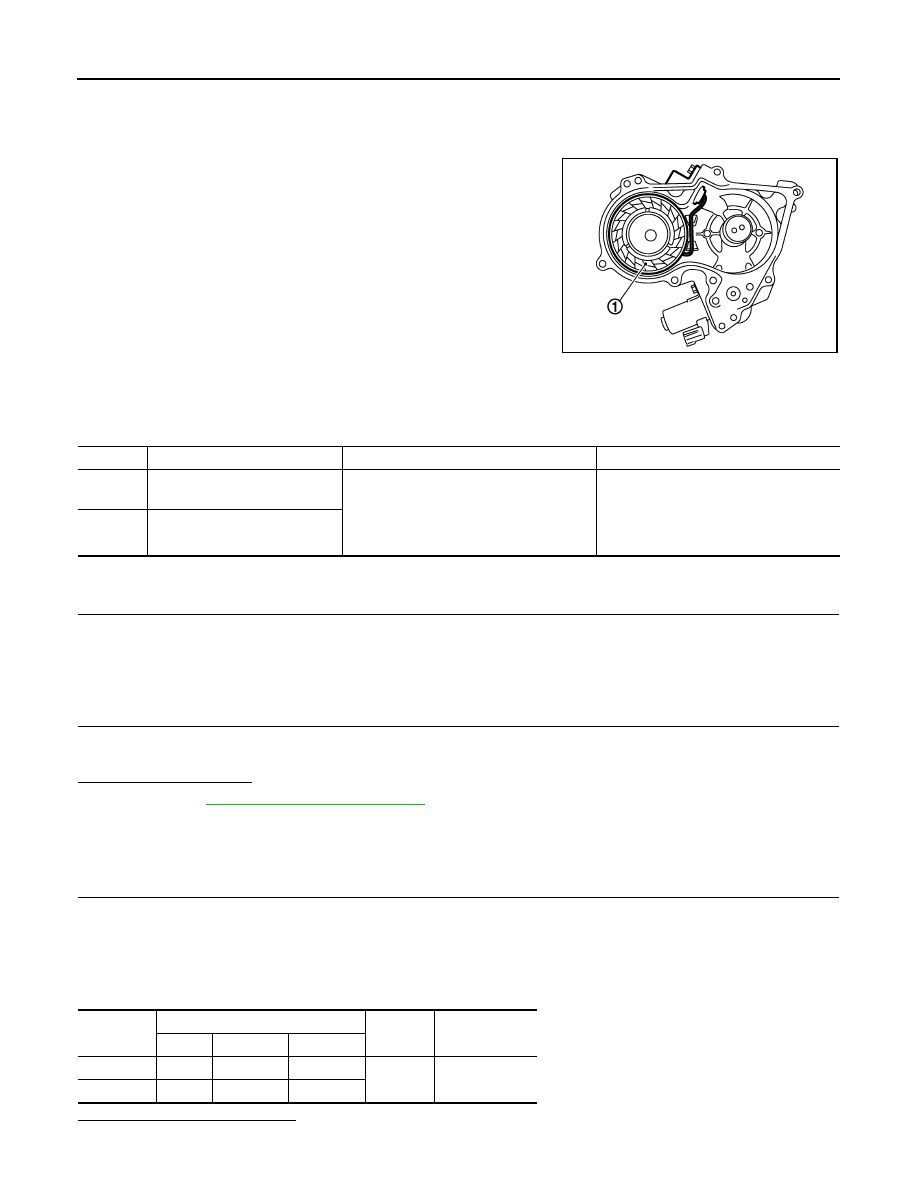
Exhaust valve timing control magnet retarder (1) controls the shut/
open timing of the exhaust valve by ON/OFF pulse duty signals sent
from the ECM.
The longer pulse width retards valve angle.
The shorter pulse width advances valve angle.

DTC Logic

INFOID:0000000003133316

DTC DETECTION LOGIC

DTC CONFIRMATION PROCEDURE

1.

PRECONDITIONING

If DTC Confirmation Procedure has been previously conducted, always turn ignition switch OFF and wait at
least 10 seconds before conducting the next test.

>> GO TO 2.

2.

PERFORM DTC CONFIRMATION PROCEDURE

1.

Start engine and let it idle for 5 seconds.

2.

Check 1st trip DTC.

Is 1st trip DTC detected?

YES

>> Go to 

EC-154, "Diagnosis Procedure"

.

NO

>> INSPECTION END

Diagnosis Procedure

INFOID:0000000003133317

1.

CHECK EXHAUST VALVE TIMING CONTROL MAGNET RETARDER POWER SUPPLY CIRCUIT

1.

Turn ignition switch OFF.

2.

Disconnect exhaust valve timing control magnet retarder harness connector.

3.

Turn ignition switch ON.

4.

Check the voltage between exhaust valve timing (EVT) control magnet retarder harness connector and
ground.

Is the inspection result normal?

YES

>> GO TO 3.

JMBIA0024ZZ

DTC No.

Trouble diagnosis name

DTC detecting condition

Possible cause

P0078

Exhaust valve timing control 
magnet retarder (bank 1) circuit

An improper voltage is sent to the ECM 
through exhaust valve timing control mag-
net retarder.

• Harness or connectors

(Exhaust valve timing control magnet 
retarder circuit is open or shorted.)

• Exhaust valve timing control magnet re-

tarder

P0084

Exhaust valve timing control 
magnet retarder (bank 2) circuit

DTC

EVT control magnet retarder

Ground

Voltage

Bank

Connector

Terminal

P0078

1

F32

1

Ground

Battery voltage

P0084

2

F41

1

P0078, P0084 EVT CONTROL MAGNET RETARDER

EC-155

< COMPONENT DIAGNOSIS >

[VQ35HR]

C

D

E

F

G

H

I

J

K

L

M

A

EC

N

P

O

NO

>> GO TO 2.

2.

DETECT MALFUNCTIONING PART

Check the following.
• Harness connectors E3, F1
• Harness for open or short between exhaust valve timing control magnet retarder and IPDM E/R

>> Repair open circuit or short to ground or short to power in harness or connectors.

3.

CHECK EXHAUST VALVE TIMING CONTROL MAGNET RETARDER OUTPUT SIGNAL CIRCUIT FOR

OPEN AND SHORT

1.

Turn ignition switch OFF.

2.

Disconnect ECM harness connector.

3.

Check the continuity between exhaust valve timing control (EVT) magnet retarder harness connector and
ECM harness connector.

4.

Also check harness for short to ground and short to power. 

Is the inspection result normal?

YES

>> GO TO 4.

NO

>> Repair open circuit or short to ground or short to power in harness or connectors.

4.

CHECK EXHAUST VALVE TIMING CONTROL MAGNET RETARDER

Refer to 

EC-155, "Component Inspection"

.

Is the inspection result normal?

YES

>> GO TO 6.

NO

>> GO TO 5.

5.

REPLACE EXHAUST VALVE TIMING CONTROL MAGNET RETARDER

1.

Replace malfunctioning exhaust valve timing control magnet retarder.

2.

Perform 

EC-19, "EXHAUST VALVE TIMING CONTROL LEARNING : Special Repair Requirement"

.

>> INSPECTION END

6.

CHECK INTERMITTENT INCIDENT

Refer to 

GI-38, "Intermittent Incident"

.

>> INSPECTION END

Component Inspection

INFOID:0000000003133318

1.

CHECK EXHAUST VALVE TIMING CONTROL MAGNET RETARDER

1.

Turn ignition switch OFF.

2.

Disconnect exhaust valve timing control magnet retarder harness connector.

3.

Check resistance between exhaust valve timing control magnet retarder terminals as follows.

Is the inspection result normal?

YES

>> INSPECTION END

NO

>> GO TO 2.

DTC

EVT control magnet retarder

ECM

Continuity

Bank

Connector

Terminal

Connector

Terminal

P0078

1

F32

2

F101

6

Existed

P0084

2

F41

2

7

Terminals

Resistance

1 and 2

9.0 - 11.0 

 [at 20

°

C (68

°

F)]

EC-156

< COMPONENT DIAGNOSIS >

[VQ35HR]

P0078, P0084 EVT CONTROL MAGNET RETARDER

2.

REPLACE EXHAUST VALVE TIMING CONTROL MAGNET RETARDER

1.

Replace malfunctioning exhaust valve timing control magnet retarder.

2.

Perform 

EC-19, "EXHAUST VALVE TIMING CONTROL LEARNING : Special Repair Requirement"

.

>> INSPECTION END

P0101, P010B MAF SENSOR

EC-157

< COMPONENT DIAGNOSIS >

[VQ35HR]

C

D

E

F

G

H

I

J

K

L

M

A

EC

N

P

O

P0101, P010B MAF SENSOR

Description

INFOID:0000000003133319

The mass air flow sensor (1) is placed in the stream of intake air. It
measures the intake flow rate by measuring a part of the entire
intake flow. The mass air flow sensor controls the temperature of the
hot wire to a certain amount. The heat generated by the hot wire is
reduced as the intake air flows around it. The more air, the greater
the heat loss. 
Therefore, the electric current supplied to hot wire is changed to
maintain the temperature of the hot wire as air flow increases. The
ECM detects the air flow by means of this current change.

DTC Logic

INFOID:0000000003133320

DTC DETECTION LOGIC

DTC CONFIRMATION PROCEDURE

1.

PRECONDITIONING

If DTC Confirmation Procedure has been previously conducted, always turn ignition switch OFF and wait at
least 10 seconds before conducting the next test.
If engine will not start or stops soon, wait at least 10 seconds with engine stopped (Ignition switch ON) instead
of running engine at idle speed.

>> GO TO 2.

2.

PERFORM DTC CONFIRMATION PROCEDURE FOR MALFUNCTION A

PBIA9559J

DTC No.

Trouble diagnosis name

DTC detecting condition

Possible cause

P0101

Mass air flow sensor 
(bank 1) circuit range/
performance

A)

A high voltage from the sensor is sent to ECM 
under light load driving condition.

• Harness or connectors

(The sensor circuit is open or 
shorted.)

• Mass air flow sensor
• EVAP control system pressure 

sensor

B)

A low voltage from the sensor is sent to ECM un-
der heavy load driving condition.

• Harness or connectors

(The sensor circuit is open or 
shorted.)

• Intake air leaks
• Mass air flow sensor
• EVAP control system pressure 

sensor

• Intake air temperature sensor

P010B

Mass air flow sensor 
(bank 2) circuit range/
performance

A)

A high voltage from the sensor is sent to ECM 
under light load driving condition.

• Harness or connectors

(The sensor circuit is open or 
shorted.)

• Mass air flow sensor
• EVAP control system pressure 

sensor

B)

A low voltage from the sensor is sent to ECM un-
der heavy load driving condition.

• Harness or connectors

(The sensor circuit is open or 
shorted.)

• Intake air leaks
• Mass air flow sensor
• EVAP control system pressure 

sensor

• Intake air temperature sensor


Content   ..  601  602  603  604   ..