Infiniti EX35. Manual - part 297


  Index      Infiniti     Infiniti EX35 - service repair manual 2008 year


Search            


Content   ..  295  296  297  298   ..


Infiniti EX35. Manual - part 297


BCS

DIAGNOSIS SYSTEM (BCM)

BCS-35

< FUNCTION DIAGNOSIS >

C

D

E

F

G

H

I

J

K

L

B

A

O

P

N

NOTE:

NOTE: 182.7 kPa (1.9 kg/cm

2

, 26 psi): Standard air pressure is for 230 kPa (2.3 kg/cm

2

, 33 psi) vehicles.

ERASE SELF-DIAGNOSIS

With CONSULT-III

1.

Perform applicable inspection of malfunctioning item and then repair or replace. 

2.

Turn ignition switch ON and select “SELF-DIAG RESULTS” mode for “AIR PRESSURE MONITOR” with
CONSULT-III.

3.

Touch “ERASE” on CONSULT-III screen to erase memory.

Without CONSULT-III

• In order to make it easier to find the cause of hard-to-duplicate malfunctions, malfunction information is

stored into the control unit as necessary during use by the user. This memory is not erased no matter how
many times the ignition switch is turned ON and OFF.

• However, this information is erased by turning ignition switch OFF after performing self-diagnostic or by

erasing the memory using the CONSULT-III.

AIR PRESSURE MONITOR : CONSULT-III Function (BCM - AIR PRESSURE MONI-
TOR)

INFOID:0000000003743942

WORK SUPPORT MODE

ID Read

The registered ID number is displayed.

ID Regist

Refer to 

WT-6, "ID REGISTRATION PROCEDURE : Special Repair Requirement"

.

SELF-DIAG RESULTS MODE

Operation Procedure

Refer to 

WT-82, "DTC Index"

.

DATA MONITOR MODE

Screen of data monitor mode is displayed.
NOTE:
When malfunction is detected, CONSULT-III perform REAL-TIME DIAGNOSIS.
Also, any malfunction detected while in this mode will be displayed at real time.

45

Transmitter battery voltage low 
(Front LH)

Battery voltage of front LH transmitter drops.

WT-29

46

Transmitter battery voltage low 
(Front RH)

Battery voltage of front RH transmitter drops.

47

Transmitter battery voltage low 
(Rear RH)

Battery voltage of rear RH transmitter drops.

48

Transmitter battery voltage low 
(Rear LH)

Battery voltage of rear LH transmitter drops.

52

Vehicle speed signal error

Vehicle speed signal error.

WT-32

53

Control unit

Tire pressure monitoring system malfunction in BCM.
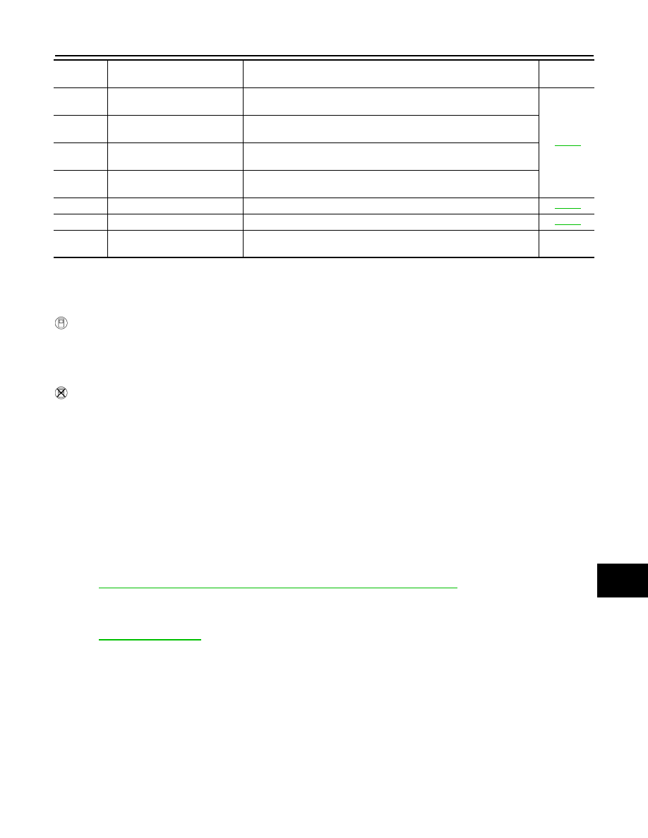
WT-33

No blinking

Tire pressure warning check 
switch

Tire pressure warning switch circuit is open.

Blinking 

pattern

Items

Diagnostic items detected when···

Check item

BCS-36

< FUNCTION DIAGNOSIS >

DIAGNOSIS SYSTEM (BCM)

Display item list

NOTE:
Before performing the self-diagnosis, be sure to register the ID, or erase the actual malfunction location may
be different from that displayed on CONSULT-III.

ACTIVE TEST MODE

NOTE:
Before performing the self-diagnosis, be sure to register the ID, or erase the actual malfunction may be differ-
ent from that displayed on CONSULT-III.

TEST ITEM LIST

Monitor

Condition

Specification

AIR PRESS FL
AIR PRESS FR
AIR PRESS RR
AIR PRESS RL

• Drive vehicle for a few minutes.

                           or

• Ignition switch ON and transmitter activation 

tool is transmitting activation signals.

Tire pressure (kPa, kg/cm

2

 or Psi)

ID REGST FL1
ID REGST FR1
ID REGST RR1
ID REGST RL1

Ignition switch ON

Registration ID: Green
No registration: Red

WARNING LAMP

Low tire pressure warning lamp ON: on
Low tire pressure warning lamp OFF: off

BUZZER

Buzzer in combination meter ON: on
Buzzer in combination meter OFF: off

Test item

Content

WARNING LAMP

This test is able to check to check that the low tire pressure warning lamp turns on.

ID REGIST WARNING

This test is able to check to check that the buzzer sounds or the low tire pressure warning lamp 
turns on.

FLASHER

This test is able to check to check that each turn signal lamp turns on.

HORN

This test is able to check to check that the horn sounds.

BCS

U1000 CAN COMM CIRCUIT

BCS-37

< COMPONENT DIAGNOSIS >

C

D

E

F

G

H

I

J

K

L

B

A

O

P

N

COMPONENT DIAGNOSIS

U1000 CAN COMM CIRCUIT

Description

INFOID:0000000003137933

CAN (Controller Area Network) is a serial communication line for real time applications. It is an on-vehicle mul-
tiplex communication line with high data communication speed and excellent error detection ability. Modern
vehicle is equipped with many electronic control unit, and each control unit shares information and links with
other control units during operation (not independent). In CAN communication, control units are connected
with 2 communication lines (CAN H-line, CAN L-line) allowing a high rate of information transmission with less
wiring. Each control unit transmits/receives data but selectively reads required data only.
CAN Communication Signal Chart. Refer to 

LAN-27, "CAN Communication Signal Chart"

.

DTC Logic

INFOID:0000000003137934

DTC DETECTION LOGIC

Diagnosis Procedure

INFOID:0000000003137935

1.

PERFORM SELF DIAGNOSTIC

1.

Turn ignition switch ON and wait for 2 seconds or more.

2.

Check “Self Diagnostic Result”.

Is “U1000: CAN COMM CIRCUIT” displayed?

YES

>> Refer to 

LAN-18, "Trouble Diagnosis Flow Chart"

.

NO

>> Refer to 

GI-38, "Intermittent Incident"

.

DTC

CONSULT-III display 

description

DTC Detection Condition

Possible cause

U1000

CAN COMM CIRCUIT

When BCM cannot communicate CAN com-
munication signal continuously for 2 seconds 
or more.

CAN communication system

BCS-38

< COMPONENT DIAGNOSIS >

U1010 CONTROL UNIT (CAN)

U1010 CONTROL UNIT (CAN)

DTC Logic

INFOID:0000000003137936

DTC DETECTION LOGIC

Diagnosis Procedure

INFOID:0000000003137937

1.

REPLACE BCM

When DTC “U1010: CONTROL UNIT (CAN)” is detected, replace BCM.

>> Replace BCM. Refer to 

BCS-84, "Exploded View"

.

DTC

CONSULT-III display de-

scription

DTC Detection Condition

Possible cause

U1010

CONTROL UNIT (CAN)

BCM detected internal CAN communication circuit malfunction.

BCM


Content   ..  295  296  297  298   ..