Infiniti EX35. Manual - part 140
AV
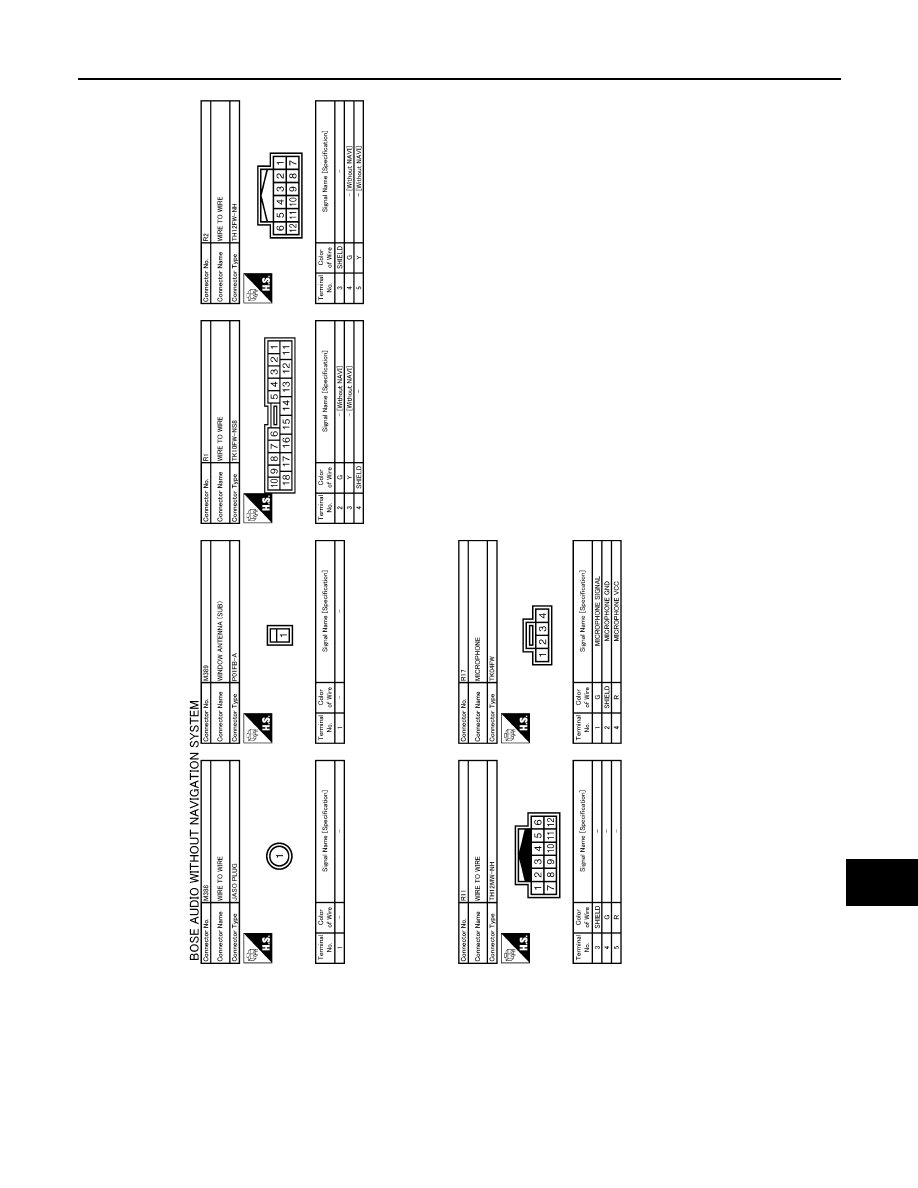
IPOD ADAPTER
AV-341
< ECU DIAGNOSIS >
[BOSE AUDIO WITHOUT NAVIGATION]
C
D
E
F
G
H
I
J
K
L
M
B
A
O
P
JCNWM0760GB
|
|
|
AV IPOD ADAPTER AV-341 < ECU DIAGNOSIS > [BOSE AUDIO WITHOUT NAVIGATION] C D E F G H I J K L M B A O P JCNWM0760GB |