Hyundai: Engine D4FA. Manual - part 142
DIESEL CONTROL SYSTEM
FLA -439
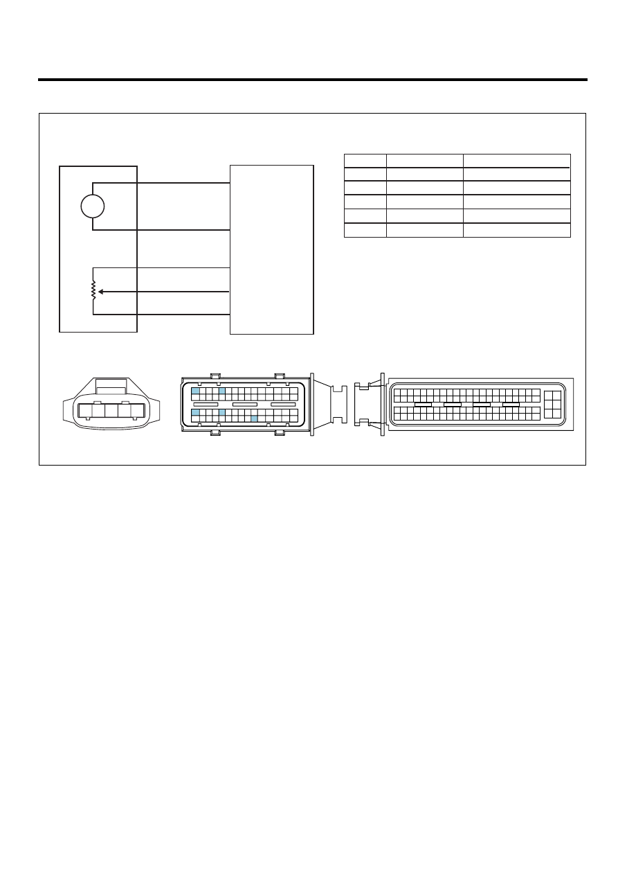
SCHEMATIC DIAGRAM
EC21A3A5
C147 Variable swirl control actuator
1
1
2
3
5
4
2
C101-1 terminal 60
MTR(+)
MTR(-)
C101-1 terminal 30
3
Power
C101-1 terminal 26
4
Feed back signal
C101-1 terminal 56
5
Feed back ground
C101-1 terminal 6
60. MTR(+)
30. MTR(-)
26. Power
56. Feed back signal
6. Feed back ground
C101-1 ECM
C147 Variable swirl control actuator
C101-2 ECM
C101-1 ECM
1
30 29
31
32
38
39
36
37
35
33
34
40
42 41
46 45 44 43
48 47
50 49
2
3
4
6
5
8
7
12 11 10 9
13
14
15
18 17
19
16
22
25
27 26
23
20
21
24
28
51
75 74
53 52
73
79 78 77 76
80
81
83 82
84
86 85
87
89 88
90
92 91
93
94
57
69 68
70
71
64
54
55
56
61
58
59
60
63 62
65
66
67
72
M
1
2
3
4
5
[CIRCUIT DIAGRAM]
[HARNESS CONNECTOR]
[CONNECTOR INFORMATION]
Terminal
Terminal
Connected to
Connected to
Function
1
2
4
3
6
5
8 7
12
13
16
17
18
23 22
20
21
19
27 26 25 24
28
29
30
14
9
10
11
15
33 32 31
34
37
41
42
40 39 38
35
36
43
44
47 46
49 48
50
53
56
58 57
54
51
52
55
59
60
45
EGNG011G