Hyundai: Engine D4FA. Manual - part 119


  Index      Hyundai     Hyundai: Engine D4FA - service repair manual


Search            


Content   ..  117  118  119  120   ..


Hyundai: Engine D4FA. Manual - part 119


DIESEL CONTROL SYSTEM

FLA -347

Fig.1

Fig.2

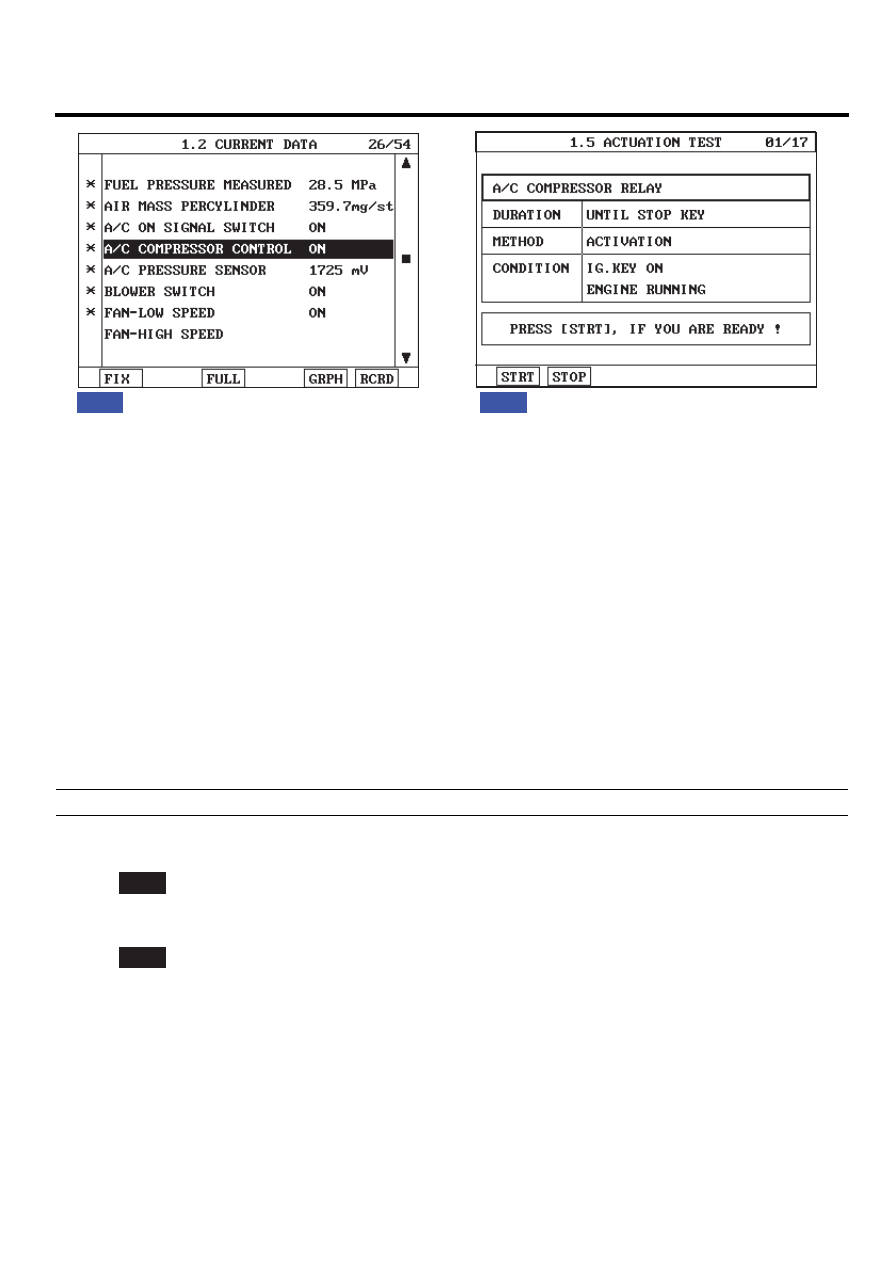
Fig.1) The operating condition of aircon relay is shown. Check if aircon compressor works properly when aircon switch is turning 
          ON.
Fig.2) Diagnosing problem of "A/C RELAY" and "AIRCON COMPRESSOR" is convenient through ACTUATION TEST on the 
          Scantool.

EGNG001C

TERMINAL AND CONNECTOR INSPECTION

E5424A6D

Refer to DTC P0646.

POWER CIRCUIT INSPECTION

E961180A

1.

Check power circuit voltage

1)

IG KEY "OFF", ENGINE "OFF".

2)

Disconnect A/C relay.

3)

Measure the voltage of A/C relay terminal 1.

specification : 11.5V~13.0V

4)

Is the measured voltage within the specification?

YES

▶ Go to "2. Check IG KEY "ON" power circuit".

NO

▶ Repair problems of 10A FUSE in engineroom junction box and related circuit and go to "Verification of Vehicle
Repair".

2.

Check IG KEY "ON" power circuit

1)

IG KEY "OFF", ENGINE "OFF".

2)

Disconnect A/C relay (E66).

3)

IG KEY "ON".

4)

Measure the voltage of glow relay terminal 3.

FLA -348

FUEL SYSTEM

specification : 11.5V~13.0V

5)

Is the measured voltage within the specification?

YES

▶ Go to "Control Circuit Inspection".

NO

▶ Repair problems of E/R FUSE & RELAY BOX 10A FUSE and related circuit and go to "Verification of Vehicle
Repair".

CONTROL CIRCUIT INSPECTION

E54456DB

1.

Check monitoring voltage in control circuit

1)

IG KEY "OFF", ENGINE "OFF".

2)

Disconnect A/C relay (E66).

3)

IG KEY "ON".

4)

Measure the voltage of glow relay terminal 5.

specification : 3.2V~3.7V

5)

Is the measured voltage within the specification?

YES

▶ Go to "Component Inspection".

NO

▶ When voltage is not detected : Go to "2. Check open in control circuit" as follows.
▶ When high voltage is detected : Repair short to battery and go to "Verification of Vehicle Repair".

2.

Check open in control circuit

1)

IG KEY "OFF", ENGINE "OFF".

2)

Disconnect A/C relay and ECM connector.

3)

Check continuity between glow relay terminal 5 and ECM connector terminal 70.

specification : Continuity ( below 1.0Ω )

4)

Is the measured resistance within the specification?

YES

▶ Repair short to ground and go to "Verification of Vehicle Repair".

NO

▶ Repair open in control circuit and go to "Verification of Vehicle Repair".

DIESEL CONTROL SYSTEM

FLA -349

COMPONENT INSPECTION

E068E6E5

1.

Check A/C relay component resistance

1)

IG KEY "OFF", ENGINE "OFF".

2)

Disconnect A/C relay.

3)

Measure the coil resistance of A/C relay.

specification : 85±5 Ω (20℃)

30

87

86

85

EGNG001H

4)

Is the measured resistance within the specification?

YES

▶ Go to "2. Check A/C relay component operation" as follows.

NO

▶ Replace A/C relay and go to "Verification of Vehicle Repair".

2.

Check A/C relay component operation

1)

IG KEY "OFF", ENGINE "OFF".

2)

Disconnect A/C relay

3)

Supplies random B+ and ground to coil sides of A/C relay ( terminal 85, terminal 86)

4)

Check continuity between A/C relay terminal 30 and terminal 87.

specification : When power is supplied : Continuity ( below 1.0Ω )
When power is not supplied : Discontinuity ( Infinite Ω )

FLA -350

FUEL SYSTEM

30

87

86

85

B+

EGNG001I

5)

Is the continuity test within the specification?

YES

▶ Go to "Verification of Vehicle Repair".

NO

▶ Replace A/C relay and go to "Verification of Vehicle Repair".

※ Repeat this process 2~3 times.

VERIFICATION OF VEHICLE REPAIR

E597F4C2

Refer to DTC P0646.


Content   ..  117  118  119  120   ..