Hyundai: Engine D4FA. Manual - part 76
DIESEL CONTROL SYSTEM
FLA -175
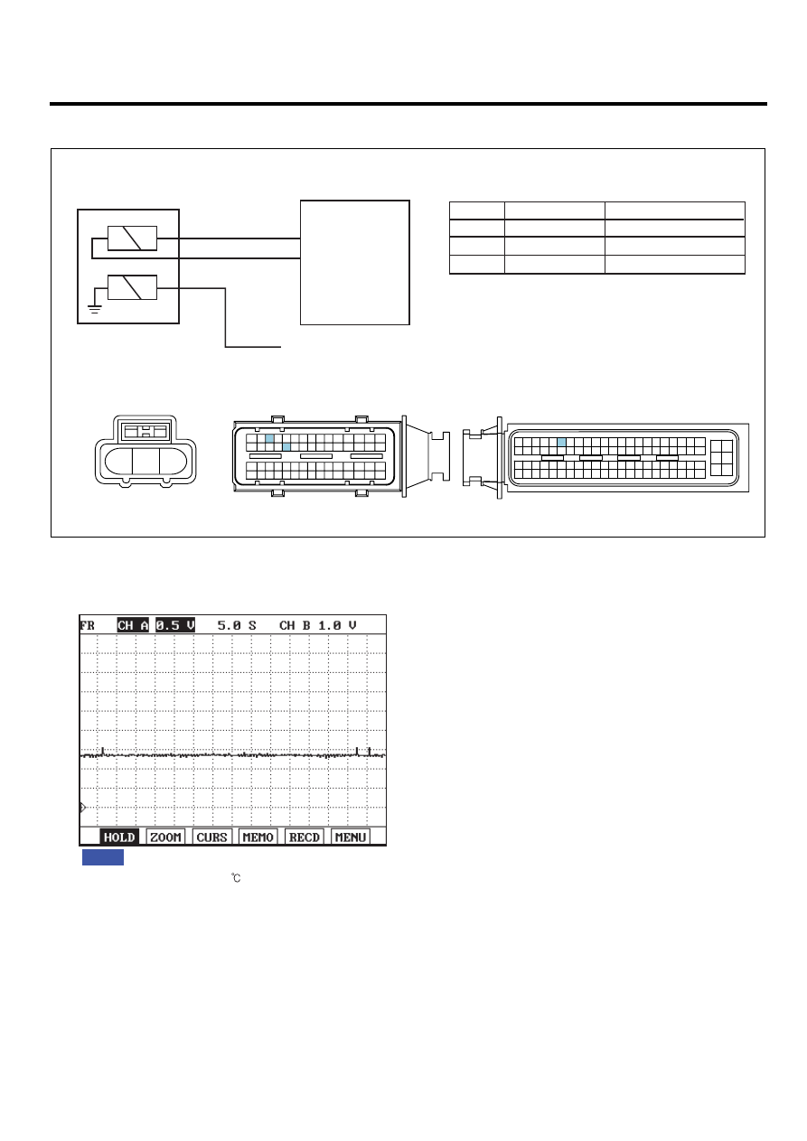
SCHEMATIC DIAGRAM
E1E39678
C127 ECTS
1
3
2
1
2
C101-1 terminal 58
Sensor signal
Water temp. gauge (Cluster)
Sensor ground
M09-3 terminal 2
3
C101-1 terminal 41
41. Sensor ground
58. Sensor signal
C101-1 ECM
C127 ECTS
Water temp. gauge (Cluster)
C101-2 ECM
C101-1 ECM
1
30 29
31
32
38
39
36
37
35
33
34
40
42 41
46 45 44 43
48 47
50 49
2
3
4
6
5
8
7
12 11 10 9
13
14
15
18 17
19
16
22
25
27 26
23
20
21
24
28
51
75 74
53 52
73
79 78 77 76
80
81
83 82
84
86 85
87
89 88
90
92 91
93
94
57
69 68
70
71
64
54
55
56
61
58
59
60
63 62
65
66
67
72
3
2
1
[CIRCUIT DIAGRAM]
[HARNESS CONNECTOR]
[CONNECTOR INFORMATION]
Terminal
Terminal
Connected to
Connected to
Function
1
2
4
3
6
5
8 7
12
13
16
17
18
23 22
20
21
19
27 26 25 24
28
29
30
14
9
10
11
15
33 32 31
34
37
41
42
40 39 38
35
36
43
44
47 46
49 48
50
53
56
58 57
54
51
52
55
59
60
45
EGNG012F
SIGNAL WAVEFORM AND DATA
E71310F8
Fig.1
Fig.1) ECTS output signal at 80
.The higher temperature rises, the lower signal voltage becomes.
EGNG012G
MONITOR SCANTOOL DATA
E7F78564
1.
Connect Scantool to Data Link Connector (DLC).
2.
Warm engine up to normal operating temperature.
3.
Turn "OFF" electrical devices and A/C.
4.
Monitor "ECTS" parameter on the Scantool.