Hyundai: Engine D4FA. Manual - part 49
DIESEL CONTROL SYSTEM
FLA -67
[IATS (INSTALLED INTO MAFS)]
Temperature℃(℉)
Resistance(kΩ )
-20
12.66 ~ 15.12
0
5.2 ~ 5.9
20
2.29 ~ 2.55
80
0.31 ~ 0.37
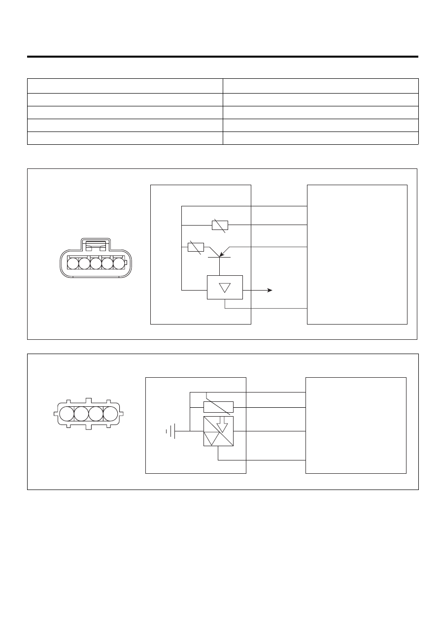
CIRCUIT DIAGRAM
C103
MAFS & IATS 1
ECM
MAFS Ground
IATS 2 Signal
MAFS Signal
MAFS current pumping
2
3
C101-1 (44)
C101-2 (89)
C101-1 (42)
C101-1 (37)
Battery (+)
5
1
4
1
2
3
4
5
EGNG112A
3
4
C101-1(23)
C101-1(53)
C101-1(13)
C101-1(40)
2
1
GROUND
5V supply
IATS1 Signal
BPS signal
BPS & IATS 2
P
C130
Harness side
1
2
3
4
EGNG114A