Hyundai: Engine D4FA. Manual - part 22


  Index      Hyundai     Hyundai: Engine D4FA - service repair manual


Search            


Content   ..  20  21  22  23   ..


Hyundai: Engine D4FA. Manual - part 22


CYLINDER HEAD ASSEMBLY

EMA -57

NOTE

Apply engine oil to the O-ring(A) of vacuum pump
shaft before assembling vacuum pump.

A

LCGF126A

11. Install the thermostat housing(A).

Tightening torque :
9.8 ~ 11.8N.m (1.0 ~ 1.2kgf.m, 7.2 ~ 8.7lb-ft)

A

ADJF046A

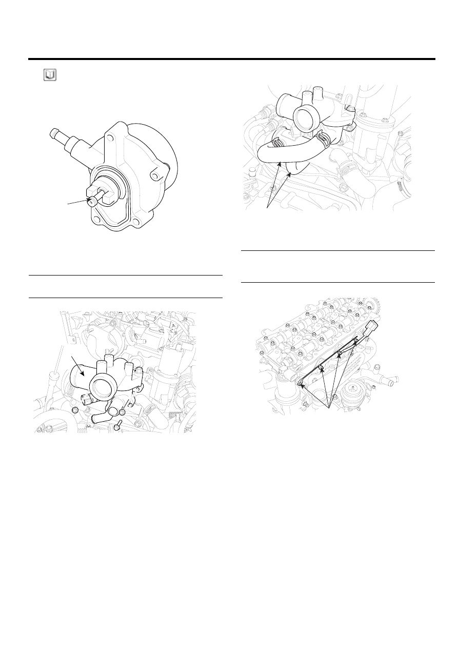
12. Reconnect the water hose(A) to thermostat housing.

A

ADJF047A

13. Install the glow plug(A) and glow plug plate.

Tightening torque :
Glow plug: 15 ~ 20N.m (1.5 ~ 2.0kgf.m, 11 ~ 14lb-ft)
Plate nut : 0.8~1.5N.m (0.08 ~ 0.15kgf.m, 0.6 ~ 1.1lb-ft)

A

LCGF041A

EMA -58

ENGINE (D4FA - DSL1.5)

14. Install the delivery pipe(A).

Tightening torque :
14.7 ~ 21.6N.m (1.5 ~ 2.2kgf.m, 10.8 ~ 15.9lb-ft)

A

LCGF040A

15. Install the intake and exhaust manifold.

(Refer to

EMA-96)

16. Install the timing chain. (Refer to EMA-25)

17. Install the drive belt.

ENGINE BLOCK

EMA -59

ENGINE BLOCK

CYLINDER BLOCK

E80C8E3F

COMPONENT

5

TORQUE : N.m(kgf.m, lbf.ft)

1.  Oil filter cap
2.  Oil filter
3.  Oil filter housing & oil cooler assembly
4.  Water pipe
5.  Clutch disk cover
6.  Clutch disk

  7.  Flywheel
  8.  Crankshaft rear oil seal
  9.  Piston & connecting rod
10.  Connecting rod bearing
11.  Connecting rod cap

12.  Bed plate
13.  Crankshaft main bearing
14.  Crankshaft
15.  Oil jet
16.  Cylinder block

6

8

1

2

3

9

10

11

14

12

19.6 ~ 24.5
(2.0 ~ 2.5, 14.5 ~ 18.1)

68.6 ~ 78.5
(7.0 ~ 8.0, 50.6 ~ 57.9)

13

32.4 ~ 36.3
(3.3 ~ 3.7, 23.9 ~ 26.8)

8.8 ~ 12.7
(0.9 ~ 1.3, 6.5 ~ 9.4)

15

16

7

19.6 ~ 26.5
(2.0 ~ 2.7, 14.5 ~ 19.5)

4

LDJF004A

EMA -60

ENGINE (D4FA - DSL1.5)

DISASSEMBLY

E69CD7DF

1.

M/T : Remove the fly wheel.

2.

A/T : Remove the drive plate.

3.

Install the engine to engine stand for disassembly.

4.

Remove the timing chain. (Refer to EMA-18)

5.

Remove the intake manifold and exhaust manifold.
(Refer to EMA-94)

6.

Remove the cylinder head. (Refer to EMA-45)

7.

Remove the water pipe(A).

A

LCGF052A

8.

Remove the oil filter and oil cooler assembly(A).

A

ACGF053A

9.

Remove the bed plate(A).

A

LCGF054A

10. Remove the rear oil seal(A).

A

LCGF055A

11. Remove the connecting rod cap(A).

NOTE

Mark the connecting rod caps to be able to reassem-
ble in the original position and direction.

A

LCGF056A


Content   ..  20  21  22  23   ..