Hyundai Tiburon (2003 year). Manual - part 201
The components which is on and off as like turn signal lamp, seat belt indicator, burglar alarm horn, chime bell
and front wiper relay are displayed "ON"while controlling.
INPUT SIGNAL ACTUATION TEST
Parking position
OUTPUT
Snow safe relay
OFF
ON
Snow safety
operation
OTHERS
OUTPUT
Power window power
OFF
ON
INPUT
Seat belt switch
Seat belt removal
Seat belt installation
OUTPUT
Seat belt indicator
OFF
ON
OUTPUT
Chime bell
OFF
ON
INPUT
Over speed signal
OFF
ON
When the vehicle
speed is over 120km
INPUT
Rear window defogger
switch
OFF
ON
OUTPUT
Rear widnow defogger
OFF
ON
On starting state
INPUT
Crash sensor
OFF
ON
On crash state
OUTPUT
Burglar alarm horn
OFF
ON
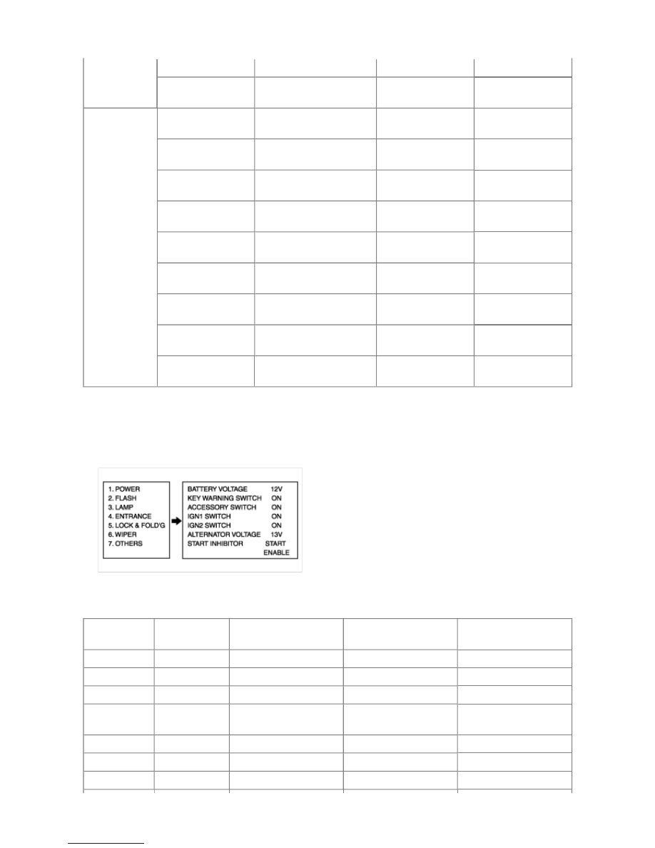
MENU COMPOSITION
1. INPUT/OUTPUT MONITORING
2. INPUT ACTUATION TEST
3. OUTPUT ACTUATION TEST
NUMBER
INPUT /
OUTPUT
NAME
OPERATION
CONDITION
1
INPUT
Turn signal switch (LH)
Turn signal lamp (LH)
2
INPUT
Turn signal switch (RH)
Turn signal lamp (RH)
3
INPUT
Hazard switch
Hazard lamp
4
INPUT
Turn signal lamp
detection current
Double flash
Turn signal lamp switch
ON
5
INPUT
Tail lamp switch
Tail lamp
6
INPUT
Auto light switch
Tail/head lamp
7
INPUT
Auto light sensor voltage
Auto light switch ON