Content .. 1645 1646 1647 1648 ..
Hummer H3. Manual - part 1647
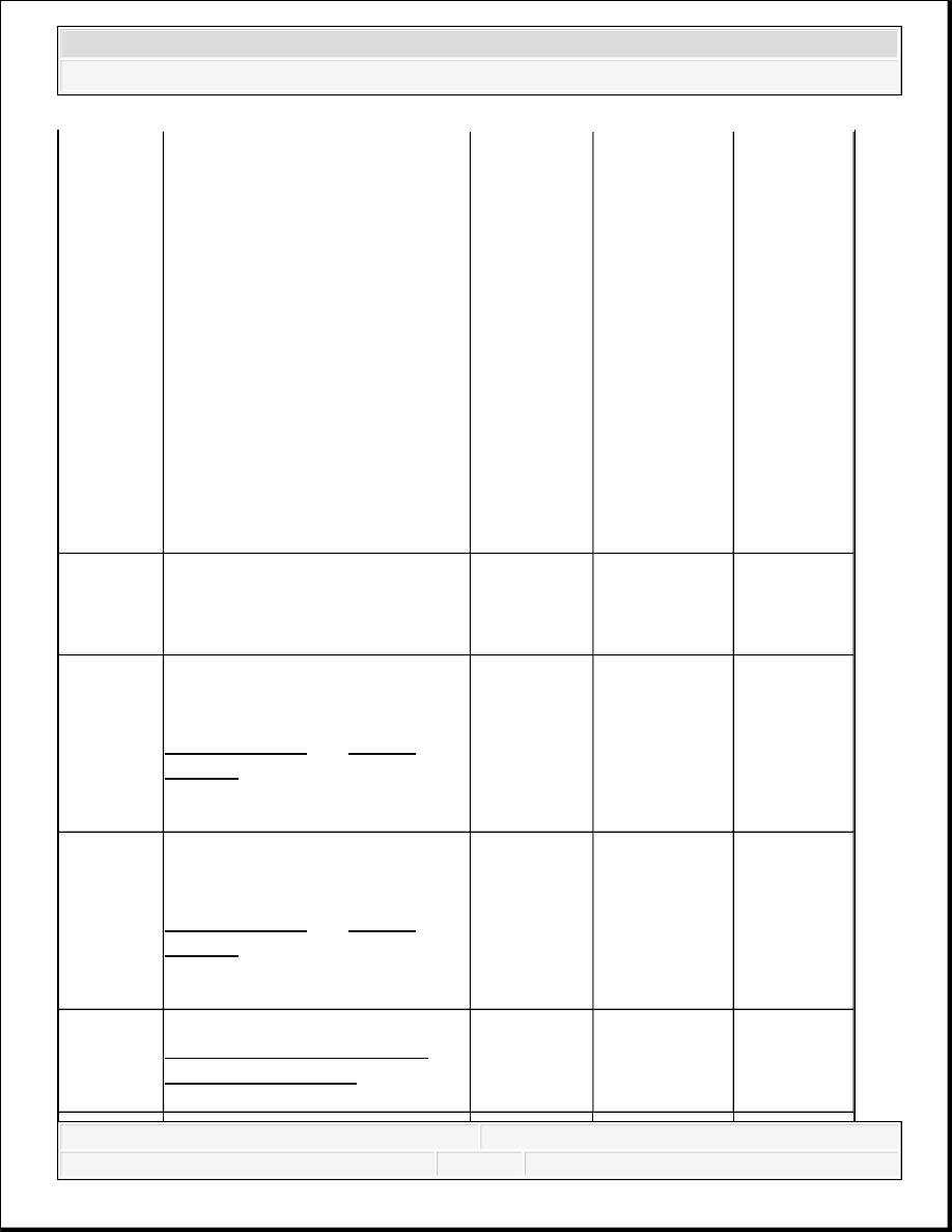
3
1. Disconnect and remove the
mode switch.
2. Connect a DMM between the
switch signal and 5 volt
reference pins on the switch.
3. Measure the resistance
through the mode switch
while pressing and holding
each of the mode buttons and
comparing values.
Does the DMM indicate all
resistance values within the
specified ranges?
Neutral
2,424-2,574
ohms
4 HI 3,553-
3,773 ohms
4 HI Lock
1,817-1,930
ohms
4 LO Lock
5,256-5,581
ohms
Differential
Lock 747-
793 ohms
Normal
16,878-
17,922 ohms Go to Step 4 Go to Step 7
4
Check the voltage on the 5-volt
reference circuit.
Was the voltage within the
specified range?
4.8-5.1 V
Go to Step 6 Go to Step 5
5
Test the 5-volt reference circuit for
an open, short to ground, short to
voltage or high resistance. Refer to
Circuit Testing and Wiring
Repairs .
Did you find and correct the
condition?
-
Go to Step 9 Go to Step 8
6
Test the switch signal circuit for a
short to voltage, short to ground,
open or high resistance. Refer to
Circuit Testing and Wiring
Repairs .
Did you find and correct the
condition?
-
Go to Step 9 Go to Step 8
7
Replace the mode switch. Refer to
Transfer Case Shift Control
Switch Replacement.
Did you complete the repair?
-
Go to Step 9
-
2007 Hummer H3
2007 TRANSMISSION Transfer Case - BW 4493/4494 - H3