Honda Ridgeline. Manual - part 493
01
SJC8A00J26370100000EAAT00
−
−
−
−
−
−
22-268
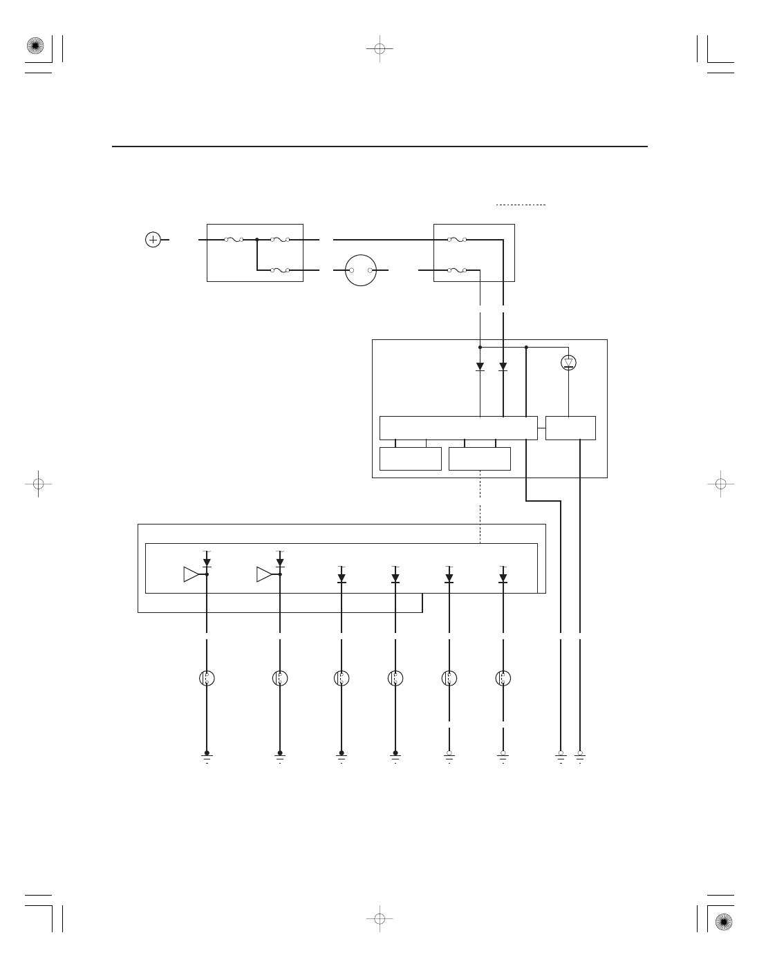
Safety Indicator System
Circuit Diagram
1
1
1
1
: Communication line
BLK/YEL
G1
D6
B4
A6
X35
N44
2
1
2
3
BLU/YEL
BLK
G601
Q7
A10
G401
BLK
GRN/WHT
GRN/YEL
E14
H13
Q11
GAUGE CONTROL MODULE
A19
A20
C10
B6
BRN/YEL
UNDER DASH FUSE/RELAY BOX
N28
BLK
G402
MICU
H12
E15
GRN
LT GRN/RED
G602
BLK
BLU/ORN
No.21 (7.5 A)
No.7 (7.5 A)
WHT/RED
UNDER DASH FUSE/RELAY BOX
No.15 (40 A)
No.22 (BAT) (120 A)
YEL
WHT
IG1
BAT
BLK/YEL
YEL
No.23 (IG) (50 A)
UNDER HOOD FUSE/RELAY BOX
BATTERY
IGNITION SWITCH
IG1 HOT in ON (II) and
START (III)
IN BED
TRUNK LID
OPEN
INDICATOR
(LED)
POWER SUPPLY CIRCUIT/
CONTROLLER AREA NETWORK CONTROLLER
DOOR MONITORS
(In the LCD display)
B CAN
TRANSCEIVER
TAILGATE
SWITCH
(Closed :
Tailgate open)
RIGHT
REAR
DOOR
SWITCH
(Closed :
Door open)
LEFT
REAR
DOOR
SWITCH
(Closed :
Door open)
FRONT
PASSENGER’S
DOOR
SWITCH
(Closed :
Door open)
DRIVER’S
DOOR
SWITCH
(Closed :
Door open)
FRONT
PASSENGER’S
DOOR
COURTESY
LIGHT
DRIVER’S
DOOR
COURTESY
LIGHT
IN BED
TRUNK LID
LATCH
SWITCH
(Closed :
Trunk lid open)
WARNING
DRIVE CIRCUIT