Honda Ridgeline. Manual - part 161


  Index      Honda     Honda Ridgeline - service repair manual 2006-2008 year


Search            


Content   ..  159  160  161  162   ..


Honda Ridgeline. Manual - part 161


01

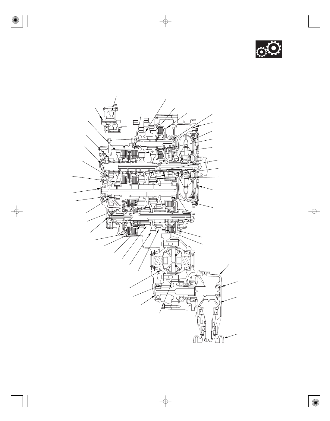
Transmission Cutaway View

14-29

REVERSE IDLER GEAR

REVERSE IDLER
GEAR SHAFT

5TH CLUTCH

4TH CLUTCH

MAINSHAFT
5TH GEAR

MAINSHAFT
REVERSE GEAR

MAINSHAFT

COUNTERSHAFT
REVERSE GEAR

REVERSE
SELECTOR HUB

COUNTERSHAFT

REVERSE SELECTOR

COUNTERSHAFT
5TH GEAR

COUNTERSHAFT
4TH GEAR

COUNTERSHAFT IDLER GEAR

1ST-HOLD CLUTCH

COUNTERSHAFT 1ST GEAR

COUNTERSHAFT 2ND GEAR

1ST CLUTCH

SECONDARY SHAFT 1ST GEAR

SECONDARY SHAFT IDLER GEAR

FINAL DRIVEN GEAR

TRANSFER DRIVE GEAR

TRANSFER OUTPUT SHAFT

INTERMEDIARY
SHAFT 4TH GEAR

INTERMEDIARY
SHAFT 3RD GEAR

3RD CLUTCH

INTERMEDIARY SHAFT

TORQUE CONVERTER

MAINSHAFT 4TH GEAR

MAINSHAFT 3RD GEAR

FINAL DRIVE GEAR

SECONDARY SHAFT

2ND CLUTCH

PARK GEAR

SECONDARY SHAFT 2ND GEAR

DIFFERENTIAL ASSEMBLY

TRANSFER ASSEMBLY

TRANSFER HYPOID
DRIVE GEAR/
SHAFT ASSEMBLY

TRANSFER
OUTPUT SHAFT
(HYPOID GEAR)

COMPANION
FLANGE

DRIVE PLATE

ONE-WAY CLUTCH

RING GEAR

(cont’d)

02

Power Flow (cont’d)

P Position

N Position

14-30

Automatic Transmission

System Description (cont’d)

INTERMEDIARY SHAFT 3RD GEAR

MAINSHAFT

COUNTERSHAFT

SECONDARY SHAFT

TORQUE CONVERTER

SECONDARY SHAFT
IDLER GEAR

FINAL DRIVEN GEAR

COUNTERSHAFT IDLER GEAR

FINAL DRIVE GEAR

MAINSHAFT 3RD GEAR

PARK GEAR

Hydraulic pressure is not applied to the clutches. Power is not transmitted to the countershaft. The countershaft is
locked by the park pawl interlocking the park gear.

Engine power transmitted from the mainshaft drives the mainshaft 3rd gear, the intermediary shaft 3rd gear, but
hydraulic pressure is not applied to the clutches. Power is not transmitted to the countershaft. In this position, the
position of the reverse selector differs according to whether the shift lever shifted from D or R:

• When shifted from D, the reverse selector engages with the countershaft 5th gear and the reverse selector hub, and

the 5th gear engages with the countershaft.

• When shifted from R, the reverse selector engages with the countershaft reverse gear and the reverse selector hub,

and the reverse gear engages with the countershaft.

03

1 Position (Acceleration)

14-31

MAINSHAFT 3RD GEAR

MAINSHAFT

COUNTERSHAFT

SECONDARY SHAFT

1ST CLUTCH

TORQUE CONVERTER

COUNTERSHAFT 1ST GEAR

SECONDARY SHAFT
1ST GEAR

SECONDARY SHAFT
IDLER GEAR

FINAL DRIVEN GEAR

TRANSFER OUTPUT SHAFT

COUNTERSHAFT IDLER GEAR

FINAL DRIVE GEAR

TRANSFER HYPOID
DRIVE GEAR/SHAFT

TRANSFER
OUTPUT SHAFT
(HYPOID GEAR)

1ST-HOLD CLUTCH

TRANSFER DRIVE GEAR

ONE-WAY CLUTCH

In the 1 position under an acceleration, hydraulic pressure is applied to the 1st clutch and the 1st-hold clutch. The
power flow when accelerating is as follows:

• Hydraulic pressure is applied to the 1st clutch, then the 1st clutch engages the secondary shaft 1st gear with the

secondary shaft by the one-way clutch.

• The mainshaft 3rd gear drives the secondary shaft via the countershaft idler gear and secondary shaft idler gear.
• The secondary shaft 1st gear drives the countershaft 1st gear and the countershaft.
• Hydraulic pressure is also applied to the 1st-hold clutch, and the 1st-hold clutch engages the secondary shaft 1st

gear with the secondary shaft.

• Power is transmitted to the final drive gear, which in turn drives the final driven gear and the transfer drive gear.
• The transfer output shaft drives the transfer hypoid drive gear/shaft and the transfer output shaft (hypoid gear).

(cont’d)

04

Power Flow (cont’d)

1 Position (Deceleration)

14-32

Automatic Transmission

System Description (cont’d)

MAINSHAFT 3RD GEAR

MAINSHAFT

COUNTERSHAFT

SECONDARY SHAFT

1ST CLUTCH

TORQUE CONVERTER

COUNTERSHAFT 1ST GEAR

SECONDARY SHAFT
1ST GEAR

SECONDARY SHAFT
IDLER GEAR

FINAL DRIVEN GEAR

COUNTERSHAFT IDLER GEAR

FINAL DRIVE GEAR

1ST-HOLD CLUTCH

ONE-WAY CLUTCH

The power flow in the 1 position when decelerating is as follows:

• Hydraulic pressure is applied to the 1st clutch and the 1st-hold clutch.
• Rolling resistance from the road surface goes through the front wheels to the final driven gear, then to the

countershaft idler gear.

• The one-way clutch disengages because the application of torque is reversed.
• The force conveyed to the secondary shaft idler gear turns the mainshaft 3rd gear via the countershaft idler gear. As

a result, engine braking can be obtained with 1st gear.


Content   ..  159  160  161  162   ..