Honda Element. Manual - part 193


  Index      Honda     Honda Element - service repair manual 2007-2008 year


Search            


Content   ..  191  192  193  194   ..


Honda Element. Manual - part 193


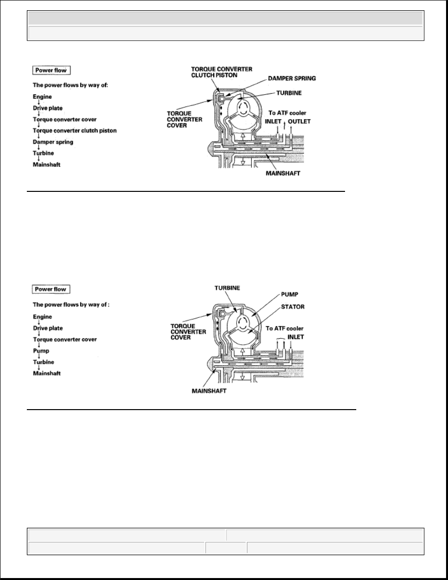
Fig. 57: Torque Converter Clutch Lock-Up On (Engaging Torque Converter Clutch) 
Courtesy of AMERICAN HONDA MOTOR CO., INC. 

Torque Converter Clutch Lock-up OFF (Disengaging Torque Converter Clutch) 

Fluid entered from the chamber between the torque converter cover and the torque converter clutch piston 
passes through the torque converter and goes out through the chambers between the turbine and the stator, and 
between the pump and the stator. As a result, the torque converter clutch piston moves away from the torque 
converter cover, and the torque converter lock-up clutch is released; torque converter clutch lock-up is OFF. 

Fig. 58: Torque Converter Clutch Lock-Up Off (Disengaging Torque Converter Clutch) 
Courtesy of AMERICAN HONDA MOTOR CO., INC. 

No Lock-up 

Shift solenoid valve E is turned OFF by the PCM, and shift solenoid valve E pressure (SE) is not applied to the 
lock-up shift valve. The lock-up shift valve stays to the right to uncover the torque converter pressure ports 
leading to the left: side of the torque converter and releasing pressure from the right side of the torque converter. 
Torque converter pressure (92) changes to (94) at the lock-up shift valve, and enters into the left side of the 
torque converter to disengage the torque converter clutch. This keeps the torque converter clutch piston keeps 
away from the torque converter cover and the torque converter clutch lock-up is OFF. 


2007 Honda Element EX 

2007-2008 TRANSMISSION Automatic Transmission - Element


Fig. 59: Hydraulic Circuit Diagram - No Lock-Up 
Courtesy of AMERICAN HONDA MOTOR CO., INC. 

Partial Lock-up 

As the speed of the vehicle reaches the programmed value, shift solenoid valve E is turned ON by the PCM, and 
shift solenoid valve E pressure (SE) is applied to the right side of the lock-up shift valve. The lock-up shift 
valve is moved to the left side to switch the torque converter pressure (91) port, which goes to the right side of 
the torque converter, and the port of torque converter pressure (94) is released from the left side of the torque 
converter. Torque converter pressure (91) flows to the right side of the torque converter to engage the torque 
converter clutch. The PCM also controls A/T clutch pressure control solenoid valve A, and A/T clutch pressure 
control solenoid valve A pressure (55) is applied to the lock-up shift valve and lock-up control valve. The 
position of the lock-up control valve depends on A/T clutch pressure control solenoid valve A pressure (55) and 
torque converter pressure released from the torque converter. The lock-up control valve controls the amount of 
torque converter clutch lock-up until fluid between the clutch piston and torque converter cover is fully 
released; the torque converter clutch is in partial lock-up. 

NOTE:

When used, "left" or "right" indicates direction on the hydraulic circuit.

NOTE:

When used, "left" or "right" indicates direction on the hydraulic circuit.


2007 Honda Element EX 

2007-2008 TRANSMISSION Automatic Transmission - Element


Fig. 60: Hydraulic Circuit Diagram - Partial Lock-Up 
Courtesy of AMERICAN HONDA MOTOR CO., INC. 

Full Lock-up 

When the vehicle speed increases, the PCM sends a signal to A/T clutch pressure control solenoid valve A to 
increase A/T clutch pressure control solenoid valve A pressure (55), and the lock-up control valve is moved to 
the left side by increased pressure. Then converter pressure (94) from the left side of the torque converter is 
completely released at the lock-up control valve, and torque converter pressure (91) engages the torque 
converter clutch securely; the torque converter clutch is in full lock-up. 

NOTE:

When used, "left" or "right" indicates direction on the hydraulic circuit.


2007 Honda Element EX 

2007-2008 TRANSMISSION Automatic Transmission - Element


Fig. 61: Hydraulic Circuit Diagram - Full Lock-Up 
Courtesy of AMERICAN HONDA MOTOR CO., INC.


2007 Honda Element EX 

2007-2008 TRANSMISSION Automatic Transmission - Element


Content   ..  191  192  193  194   ..