Honda Element. Manual - part 140


  Index      Honda     Honda Element - service repair manual 2007-2008 year


Search            


Content   ..  138  139  140  141   ..


Honda Element. Manual - part 140


SRS INDICATOR DOES NOT COME ON

1. Turn the ignition switch ON (II), and see if the other indicators come on (brake system, etc). 

Do the other indicators come on?  

YES -Go to step 2. 

NO -Go to step 9. 

2. Turn the ignition switch OFF, then remove the gauge control module (see REWRITING THE ODO 

DATA AND TRANSFERRING MAINTENANCE MINDER ON A NEW GAUGE CONTROL 
MODULE
 ). Disconnect the gauge control module (36P) connector (A) from the gauge control module. 

Fig. 233: Identifying Gauge Control Module (36P) Connector 

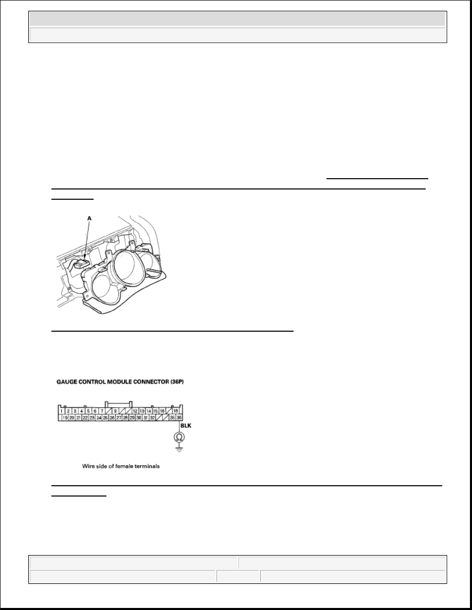
3. Measure the resistance between the No. 36 terminal of gauge control module connector (36P) and body 

ground. There should be 0-1.0 ohms. 

Fig. 234: Measuring Resistance Between Gauge Control Module Connector (36P) Terminal 36 And 
Body Ground
 

Is the resistance as specified?  

YES -Go to step 4. 


2007 Honda Element EX 

2007-08 RESTRAINTS SRS (Supplemental Restraint System) - Element


NO -Open in the BLK wire of dashboard wire harness A, or faulty body ground terminal (G502) (see 
DASHBOARD WIRE HARNESS A (RIGHT BRANCH) ). If the body ground terminal is OK, replace 
dashboard wire harness A. 

4. Measure the voltage between the No. 12 terminal of the gauge control module connector (36P) and body 

ground within the first 6 seconds after turning the ignition switch ON (II). There should be about 1.0 V 
for 6 seconds and then more than 8.5 V. 

Fig. 235: Measuring Voltage Between Gauge Control Module Connector (36P) Terminal 12 And 
Body Ground
 

Is the voltage as specified?  

YES -Faulty SRS indicator circuit in the gauge control module; replace the gauge control module. 

NO -Go to step 5. 

5. Turn the ignition switch OFF, Disconnect the battery negative cable, and wait for 3 minutes.  

6. Disconnect SRS unit connector A (28P) from the SRS unit (see step 9 on ).  

7. Reconnect the battery negative cable.  

8. Connect a voltmeter between the No. 12 terminal of gauge control module connector (36P) and body 

ground. Turn the ignition switch ON (II), and measure the voltage. There should be 0.5 V or less. 

Fig. 236: Measuring Voltage Between Gauge Control Module Connector (36P) Terminal 12 And 
Body Ground


2007 Honda Element EX 

2007-08 RESTRAINTS SRS (Supplemental Restraint System) - Element


Is the voltage as specified?  

YES -Faulty SRS unit; replace the SRS unit (see SRS UNIT REPLACEMENT ). 

NO -Short to power in the GRN wire of dashboard wire harness A or dashboard wire harness B; replace 
the faulty harness. 

9. Turn the ignition switch OFF. Check the No. 10 (7.5 A) fuse in the under-dash fuse/relay box. 

Is the fuse blown?  

YES -Go to step 11. 

NO -Go to step 10. 

10. Connect a voltmeter between the No. 2 terminal of the gauge control module connector (36P) and body 

ground. Turn the ignition switch ON (II), and measure the voltage. There should be battery voltage. 

Fig. 237: Measuring Voltage Between Gauge Control Module Connector (36P) Terminal 2 And 
Body Ground
 

Is there battery voltage?  

YES -Faulty SRS indicator circuit in the gauge control module or poor connection at the gauge control 
module connector (36P) and the gauge control module; if the connection is OK, replace the gauge control 
module. 

NO -Open in the under-dash fuse/relay box No. 10 (7.5 A) fuse circuit, or open in the YEL wire of 
dashboard wire harness A. If the under-dash fuse/relay box is OK, replace dashboard wire harness A. 

11. Replace the No. 10 (7.5 A) fuse, then check to see if the indicator comes on. 

Does the indicator come on?  

YES -The system is OK at this time. 


2007 Honda Element EX 

2007-08 RESTRAINTS SRS (Supplemental Restraint System) - Element


NO -Do the gauge control module self-diagnostic test (see SELF-DIAGNOSTIC FUNCTION ). If the 
gauge control module test is OK, repair a short to ground in the under-dash fuse/relay box No. 10 (7.5 A) 
fuse circuit. 

SRS INDICATOR STAYS ON, BUT NO DTCS ARE STORED 

1. Disconnect the battery negative cable, and wait for 3 minutes.  

2. Disconnect SRS unit connector A (28P) from the SRS unit (see step 9 on ).  

3. Remove the gauge control module (see REWRITING THE ODO DATA AND TRANSFERRING 

MAINTENANCE MINDER ON A NEW GAUGE CONTROL MODULE ). Disconnect the gauge 
control module (36P) connector (A) from the gauge control module. 

Fig. 238: Identifying Gauge Control Module (36P) Connector 

4. Measure the resistance between the No. 12 terminal of gauge control module connector (36P) and the No. 

11 terminal of SRS unit connector A (28P). There should be 0-1.0ohms. 

NOTE:

A new SRS unit must sense the entire system is OK before completing its 
initial self-test. The most common cause of an incomplete self-test is the 
failure to replace all deployed parts after a collision, in particular seat belt 
tensioners (see COMPONENT REPLACEMENT/INSPECTION AFTER 
DEPLOYMENT ).  

A battery/system voltage above 15.2 V can cause the SRS indicator to 
come on without storing any DTCs.  


2007 Honda Element EX 

2007-08 RESTRAINTS SRS (Supplemental Restraint System) - Element


Content   ..  138  139  140  141   ..