Great Wall Hover. Manual - part 75
Brake-21
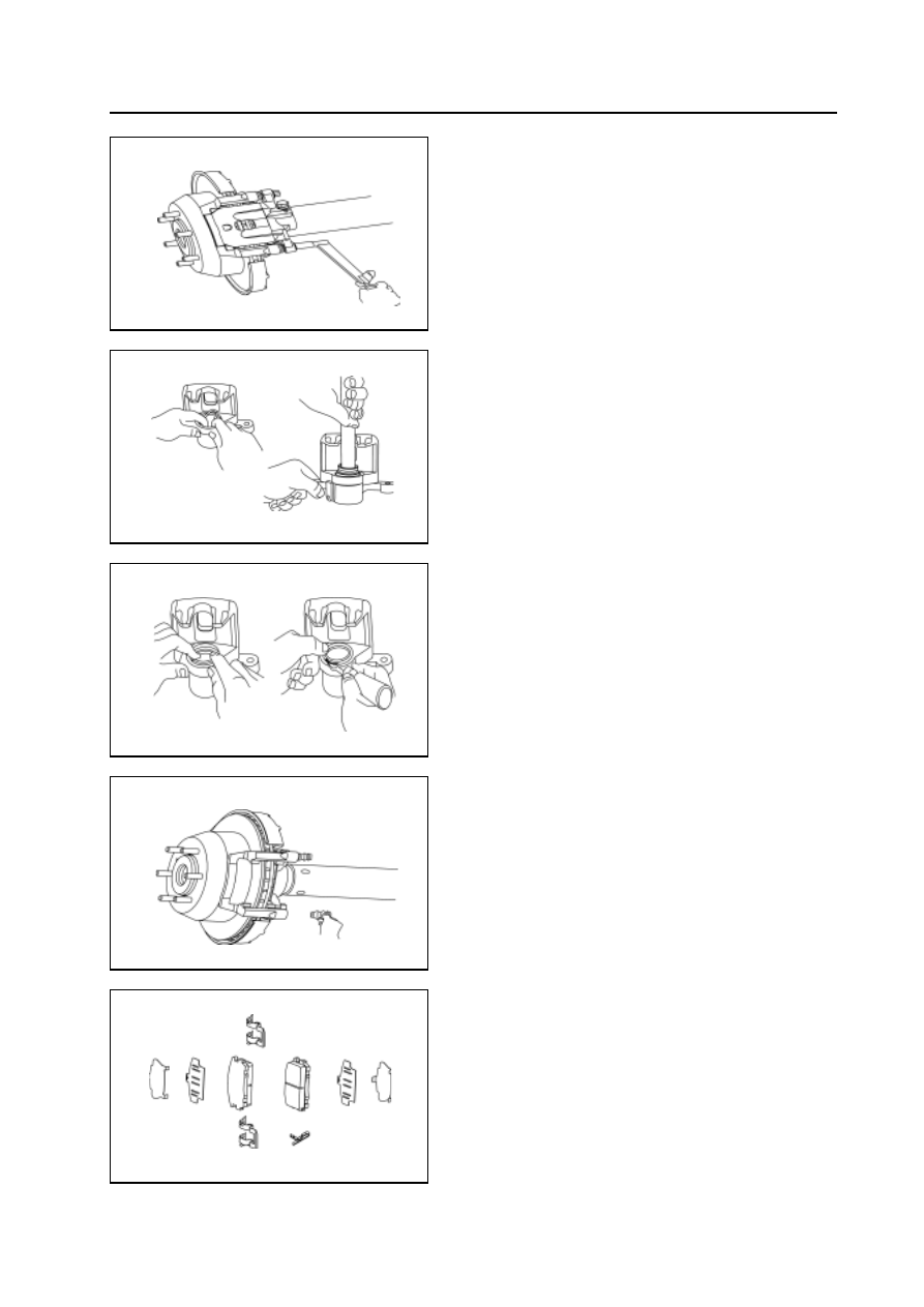
Assembly of pump
1. During the assembly, coat the guide pin with the proper vacuum
sili con based grease; coat the operating surface of piston and
square gasket with proper rubber lubricant.
2. Install the piston gasket and piston in the tong
3. Install the cylinder hole dustproof cover and wire clip in the
tong.
4. Install the rubber pin cover on the tong bracket.
Installation of brake caliper
1. Install the brake block