Great Wall Hover. Manual - part 20


  Index      Great Wall     Great Wall Hover - service repair manual


Search            copyright infringement  


Content   ..  18  19  20  21   ..


Great Wall Hover. Manual - part 20


Automatic transmission-11
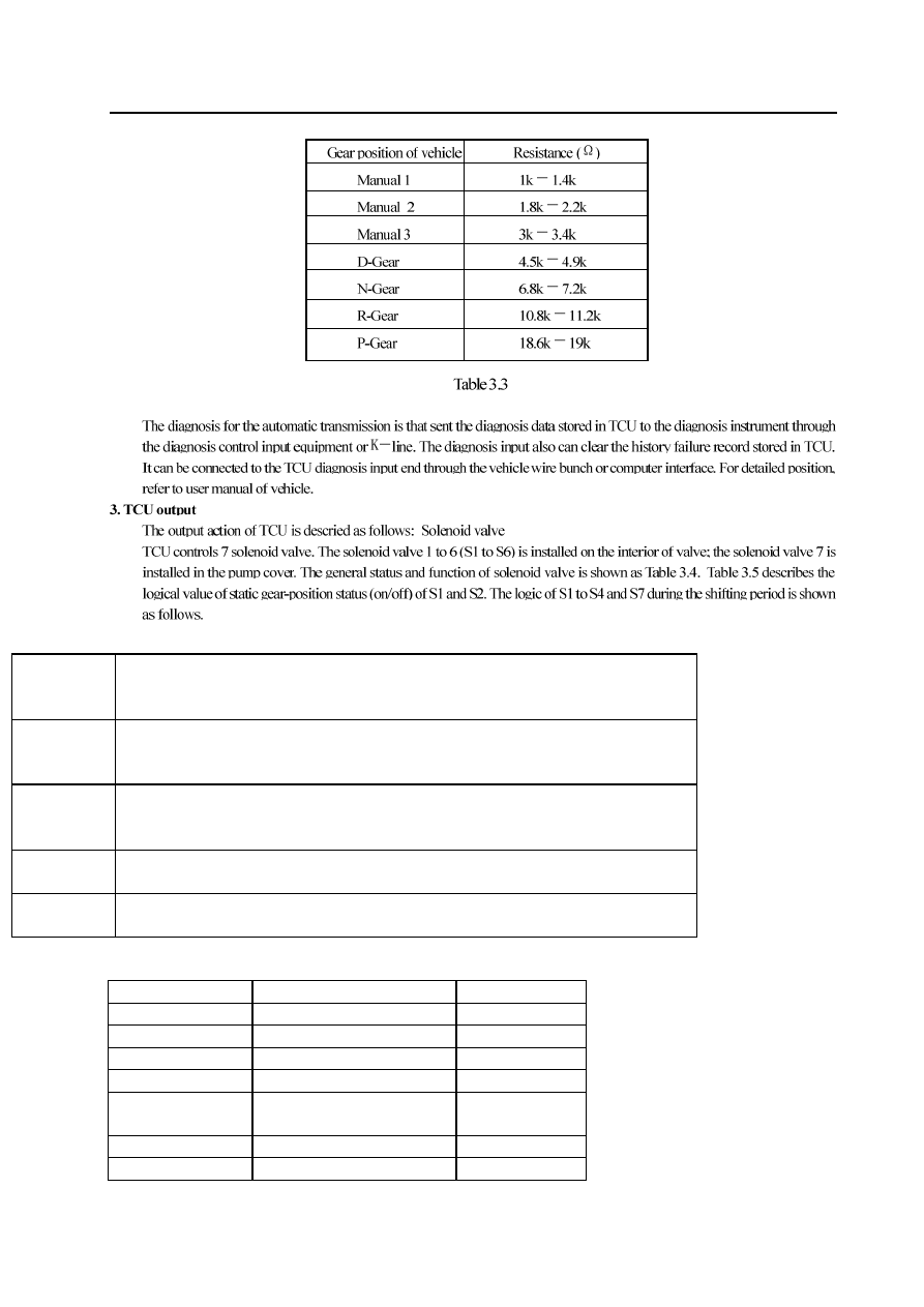
Diagnosis input

solenoid valve 

1and 2 

S1 and S2 is the normal open solenoid valve, which is used to set the gear-position with other switch 

solenoid valve. It determines the static gear-position by operating the gear shift valve. Refer to Table 3.5, 
S1 and S2 also send the pressure single to allow or prohibit the engagement with rear brake belt.   

solenoid valve 

3and 4 

S3 and S4 are the normal-opened solenoid valve which is used to control the shifting quality and sequence in 
combination. S3 control the open or close of the clutch. S4 is used to control the on and off of the front brake 
belt regulating valve.   

solenoid valve 5 

S5 is the variable pressure solenoid valve which can release the pressure of gear-position shifting. It provides 
the pressure signal to the clutch and brake belt regulator and controls the shifting pressure. S5 also provides 
the pressure single to the torque converter clutch regulating valve. 

solenoid valve 6 

S6 is the normal-opened solenoid valve, which is used to the set the H/L level of pipeline pressure. The 
pipeline pressure is high when the solenoid valve is closed. 

solenoid valve 7 

S7 is the normal-opened solenoid valve which is used to control the engagement status of torque converter 
licking clutch. It makes the clutch to generate the action when the S7 is in opened status. 

Table 3.4 Status and function of solenoid valve 
 

Gear-position S1 

S2 

1

st

-Gear On  On 

2

nd

-Gear Off  On 

3

rd

-Gear Off  Off 

4

th

-Gear On  Off 

R-Gear 

One of them is in On position 

at least. 


N-Gear Off  Off 

P-Gear Off  Off 

Table 3.5 Logic status of solenoid valve in static gear-position

Automatic transmission-12


Shifting 

Initial shifting status 

Current variation of S5 

Finished shifting status 

1-2 

S1 Off 

S4 On 

950mA-650mA 


S4 Off 


1-3 

S1 Off 

S2 Off 

S3 On 

S4 On 

900mA-400mA 


S3 Off 

S4 Off 

1-4 

S2 Off 

S3 On 

S4 On 

850mA-750mA 


S3 Off 

S4 Off 

2-3 

S2 Off 

S3 On 

S4 On 

700mA-200mA 


S3 Off 

S4 Off 

3-4 

S1 On 

S4 On 

950mA-550mA 


S4 Off 


4-3 S4 

On 

950mA-700mA 

S1 Off 

S4 Off 

4-2 S3 

On 

800mA-500mA 

S1 Off 

S2 On 

S3 Off 

4-1 

S3 On 

S4 On 

1000mA-600mA 


S2 On 

S3 Off 

S4 Off 

3-2 

S2 On 

S4 On 

550mA-400mA @ 20kph 

800mA-600mA@60kph 

1000mA-800mA@100kph 

S4 Off 

3-1 

S3 On 

S4 On 

1000mA-750mA 

S1 On 

S2 On 

S3 Off 

S4 Off 

2-1 S4 

On 

1000mA-500mA 

S1 On 

S4 Off 


Torque converter clutch 

On 

Off 

S7 On 

1000mA-500mA 

900mA-600mA 

S7 Off 


Table 3.6 Operation of solenoid valve during shifting period 

Automatic transmission-13

Symbol of solenoid valve (On/off solenoid valve)

Figure 3.5 Normal-opened type

1.Variable pressure regulating valve regulating system

The shifting pressure of abrasion unit is controlled by the variable pressure regulating valve.
 The line pressure is independent of the shifting pressure and determined by the thro
 position, shifting status and engine speed.
 S5 is a proportional or variable pressure regulating valve which provides the pressure signal control shifting pressure for
 the clutch and brake belt regulating valve.
In automatic shifting period, it process the integral times enlarging and contracting
regulation for the clutch regulating valve, brake belt regulating valve, torque converter regulating valve and VPS.
The hydraulic pressure generated by variable pressure regulating valve is in inverse ratio with current. During the shifting, TCU
will increase or decrease the current of solenoid valve according to the program. The current is variable in the range of 200mA
to 1000mA. The increasing of the current will decrease the S5 output pressure; the decreasing of current will increase the output
pressure of S5.
Lin 500 pressure (about 440 to 560kPa) is the reference pressure of VPS, meanwhile, the VPS output pressure equals to the
pressure on line 500 always.
When the VPS is in waiting status, it means there is not the generation of shifting action. VPS current is 200mA. At this time,
it gives the maximum output pressure.
In stable status, the brake belt and clutch regulating solenoid valve is in closed status. In this condition, the pressure of line 500
is applied on the piston. For the line 500 pressure is more than S5 pressure always, so it pushed the oil in S5 to the place
between the regulating valve and piston. At this time, oil pressure applied on the friction unit equals to the product of pressure
on line 500 and magnification factor.
During the starting of shifting, the used on/off solenoid valve is in opened status which cut off the oil loop supply from line 500
to piston.
At the same time, VPS pressure is decreased to starting pressure valve, pressure set by regulating valve and pressure setting
value required by execution of VPS by pushing the piston from the valve. The shifting is finished through the on/off solenoid
valve, VPS returns to the waiting status
Pointed to each gear-position, the system can make the brake belt; clutch or both realize
the electronic control.
Mode indicator lamp: the mode indicator lamp can be used to indicate the current selected and whether the overpeed status
exists. The mode indicator lamp is located in instrument panel generally.  (Refer to Part 2.3)

Automatic transmission-14

The main box includes:


 BIR blow-off valve

1. Valve

Figure 3.7 shows the valve unit in the view of transmission fluid tank. Figure 3.8 illustrates the pump cover.

2. Manual-operated valve

The manual-operated valve (refer to Figure 3.9) is connected to the car gear selection mechanism. It controls the transmission
fluid flow to the forward or reverse loop. Except in manual 1st-Gear position, the function of manual-operated valve is same
in all forward gear. In manual 1st-Gear, the transmission fluid will enter into the shift valve 1 2 to make the rear brake belt

and C4 overspeed gear clutch is engaged respectively.

The hydraulic control system is located in the valve, pump and main box.
The valve includes the following types:

Manual-operated valve               

 Three shift valves

sequence valve               electromagnetic pressure control valve
line pressure control valve
clutch connection regulating valve
brake belt connection regulating valve
solenoid valve 1 to solenoid valve 6
reverse lock valve

The pump includes the following types:

primary regulating valve  (control line pressure)
torque converter clutch regulating valve
torque converter clutch control valve


 solenoid valve 7

Hydraulic control system


Content   ..  18  19  20  21   ..