Great Wall Florid. Manual - part 28


  Index      Great Wall     Great Wall Florid - service repair manual 2008 year


Search            copyright infringement  


Content   ..  26  27  28  29   ..


Great Wall Florid. Manual - part 28


GWFLORID Maintenance Manual

110

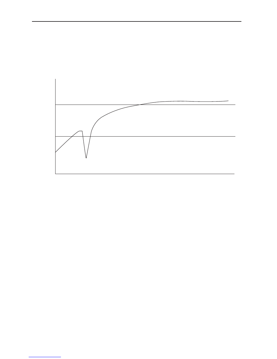
The X431 scanner possesses a waveform function. Wheel speed signal error (wheel speed sensor failure) 

only appears when intermittent problems occure, such as high speed. When in use, some signal errors may 

occasionally appear. Continue observing the waveform to make sure there is nothing abnormal.When driving 

the vehicle on a flat and straight road, all four wheels' speed sensor waveform are extremely similar. One can 

compare the two front wheels' with the two rear wheels' signal wave at the same time.

Mechanical causes:

Signal gear distortion, loosened hub bearings, smudges on the sensor surface, etc, all may lead to wheel speed 

signal intermittency and inaccuracy. Failure examples: 

As shown above, once the intermittent failures with the wheel's speed sensor signal are detected, the ABS 

control unit records the sensor problems and lights up the warning lamp.

4.  Wheel speed sensor velocity failure (ECU detects an excessive difference between the two wheels' 

speed sensor signals).

Possible causes are the gear's wheel speed sensor gap is overly large, or the wheel speed sensor signal is 

experiencing interference. For this, first determine which sensor is emitting the signal, and then use failure 

three's maintenance methods.

Areas of Importance

1.  Sometimes, in order to determine whether there is a common brake system problem or an ABS 

problem, the ABS must be terminated by pulling out its ABSECU connector or fuse. At this time the 

ABS/EBD loses function as well. On muddy, icy, or snowy roads, the vehicle may fishtail or slide, in 

which cases one must be extremely careful to avoid hard braking.

2.  The ABS malfunction rate is extremely low, when the brake system shows any problem (before the 

warning lamp goes on), first eliminate the normal brake system problems, then consider the ABS  mal-

functions.

3.  When raining or on gravel, this adjusting process is longer than the standard process, because this 

kind of road's unstable adhesion coefficient will lead to a difference between the sliding measurement 

and calculation procedures, thus it is necessary to remind drivers to be especially careful when driving 

under the circumstances mentioned above.

4.  ABSECU Areas of Importance:

(a)  The ABSECU is easily damaged from impacts or collisions, thus pay attention to ensure the ECU avoids 

such incidents.

(b)  High temperature environments can also easily damage the ECU, so when the vehicle undergoes hot paint 

work, make sure to first take the ECU out of the vehicle.

(c)  When the power switch is ON, do not disassemble the system's electrical elements and wire harness plugs, 

in order to avoid damage to the ECU. If removal or installation must be carried out, be sure to disconnect 

the ignition switch firstly. When welding components or circuits to the system, the wire harness plug 

V( Km/h)

60

30

Signal interrupt

t

111

Brake System

ABS trouble code list

Trouble code

Fault description

C0035

Front wheel speed sensor LH circuit failure, velocity failure

C0040

Front wheel speed sensor RH circuit failure, velocity failure

C0045

Rear wheel speed sensor LH circuit failure, velocity failure

C0050

Rear wheel speed sensor RH circuit failure, velocity failure

C0060

Front ABS outlet solenoid valve LH failure

C0065

Front ABS inlet solenoid valve LH failure

C0070

Front ABS outlet solenoid valve RH failure

C0075

Front ABS inlet solenoid valve RH failure

C0080

Rear ABS outlet solenoid valve LH failure

C0085

Rear ABS inlet solenoid valve LH failure

C0090

Rear ABS outlet solenoid valve RH failure

C0095

Rear ABS inlet solenoid valve RH failure

C0110

Pump motor circuit failure, operational error

C0121

Solenoid valve relay circuit failure

C0161

Brake switch circuit failure

C0245

Wheel speed sensor frequency error, wheel speed sensor signal failure

C0287

Acceleration sensor failure

C0550

ECU failure

C0800

Voltage fault, voltage too high or too low

C0232

Warning lamp positive short circuit, warning lamp ground short circuit 

should also be removed from the ECU.

(d)  Do not let oil contaminate the ECU. Be especially careful of the ECU terminals, otherwise it might obstruct 

the connection among terminals of the wire harness plug.

Note: The BOSCH ABS8.0 hydraulic pressure unit (integrated into the ECU) is not serviceable. If 

damaged, the whole unit must be replaced.

GWFLORID Maintenance Manual

112

Steering Knuckle and Hub Brake Assembly

Components

 Disposable parts

Steering knuckle and hub brake assembly 
examination and disassembly

1.  Hoist the vehicle and remove the wheels.

2.  Loosen the riveted areas of the front drive shaft nut 

and remove the nut.

3.  Inspect the front brake disc plate surface runout.

When measuring, tighten the two wheel nuts' symmetrical 

locations. The front brake disc's brake linings runout on the 

two sides should be no more than 0.11 mm. If oversized, 

they should be repaired or replaced.

4.  Inspect front brake disc thickness.

Standard thickness: 22.0 mm 

Minimum thickness: 20.0 mm

The brake disc must be changed when it reaches the minimum 

level of thickness.

Front brake caliper assembly LH

Copper washer

Hollow bolt

♦Heavy duty spring washer

Snap ring for hole 72

♦Front hub 

bearing assembly

Left steering knuckle

Left brake disc cover

♦Hexagon head bolt and 

spring washer subassembly

Wheel bolt

Front hub flange

Front brake disc

100 ± 10

: Specified torque

N·m

9 ± 2

113

Brake System

5.  Remove the front brake caliper.

Unscrew the fastened front brake caliper's bolt to remove the 

brake caliper.

Caution: Remove the front brake caliper and use wire 

or similar objects to firmly secure the brake caliper. 

(Avoid excessive twisting, bending, or pulling off the 

brake pipeline).

6.  Remove the front brake disc.

After driving the vehicle for some time, it may be hard to 

remove the brake discs. In this case, screw two M8 bolts 

into the removed brake disc's threaded holes (refer to the left 

picture for locations), and use a wrench to alternately turns 

the two bolts, thereby ejecting the brake disc.

7.  Inspect the front brake disc.

Inspect the wear and tear of the front brake disc. If the 

brake disc has obvious scuffing, the plate surface runout 

is oversized, or its thickness is smaller than the minimum 

thickness, the brake disc should be replaced.

8.  Remove the front brake disc cover.

Remove the fastened brake disc cover bolts with a wrench, and 

remove the front brake disc cover.

9.  Remove the steering knuckle's front hub bearing and 

front hub flange assembly.

Suggestion: The steering knuckle's front hub bearing and 

front hub flange assembly, under normal circumstances, 

should not undergo disassembly. If determined to have a 

problem, it should be replaced in its entirety.

10. Inspect the steering knuckle's front hub bearing and 

front hub flange assembly.

(a)  Use dye penetrant to inspect the steering knuckle for 

cracks, deformities, and damage. If found, replace the 

part.

(b)  Rotate the front hub flange and examine the bearing for 

flexible rotation. Also make sure there is no appearance 

of clamping.

(c)  Measure the front hub flange plate surface runout.

Caution: Runout should not exceed 0.03 mm.


Content   ..  26  27  28  29   ..