Geely Diagnosis Flow. Manual part - 33


  Главная      Geely     Common Malfunction Diagnosis Flow of Geely Automobile - 2008 year


поиск по сайту            


содержание   ..  30  31  32  33  34  ..


Geely Diagnosis Flow. Manual part - 33


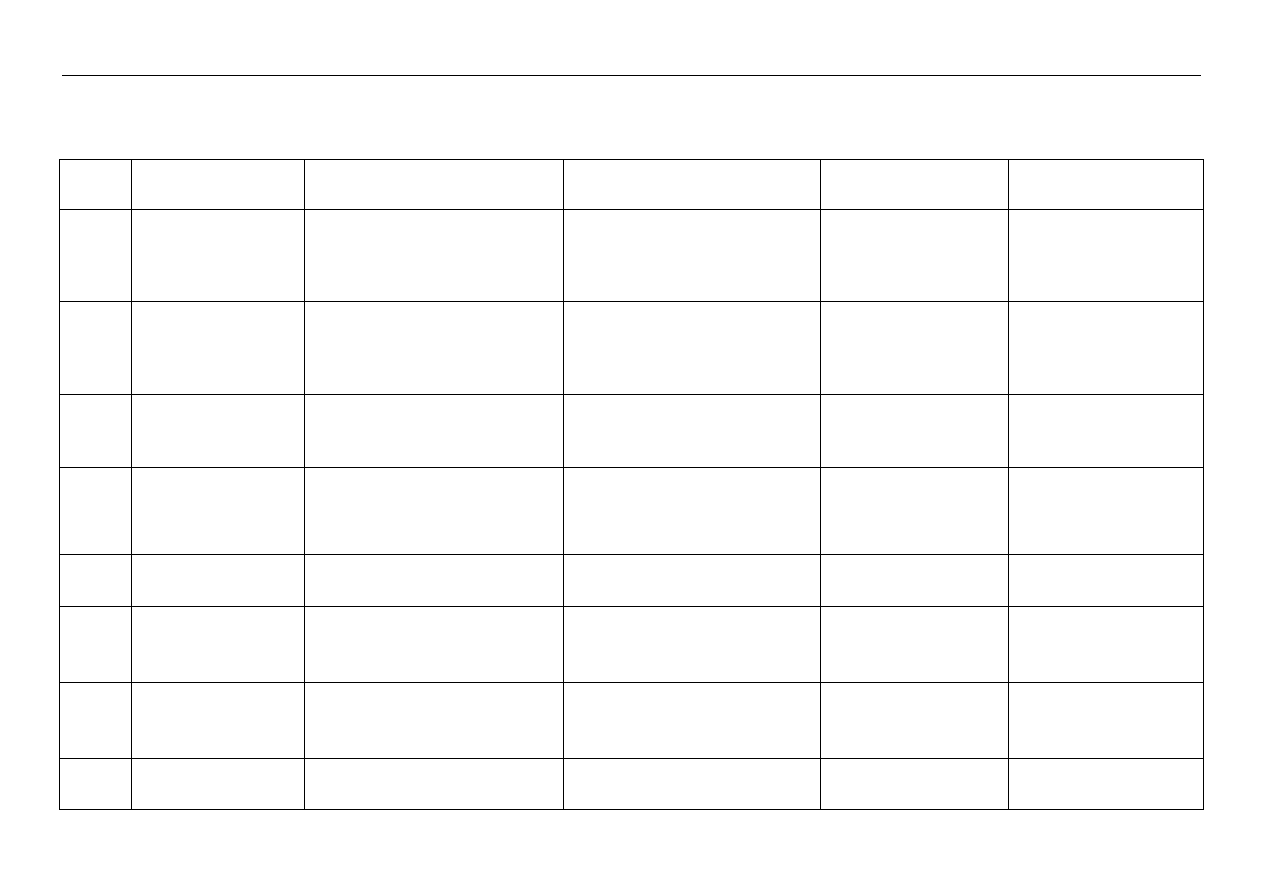
129 

No.068 Diagnosis and solution of common malfunctions of JL376/378QE engine’s electric control system   


Serial No.  Malfunction   

Display by diagnosis instrument Analytic 

procedure 

Causes  

Measures  

1. 

After startup, flame out 
after about 10s at idling 
speed. Hard to start again, 
and flame out when 
throttling up the engine 

λ integral quantity exceeding lower limit 
oil injection correction: -25% 
voltage of oxygen voltage is 800mv 

Obviously oil injection not normal; check 
hardware of oil supply system is working 
normally  

ECU malfunction; malfunction 
disappears after replacement 
of ECU 

Replace ECU 

2. 

Unable to startup (started 
before); normally started 
once during exhaust 

Diagnosis instrument ON, but unable to 
communicate with ECU 

Key placed to the second position, and 
check ECU27 pin is with 12V voltage, 19 
pin is connected to vehicle body 

Fuse broken, causing ECU27 
pin without voltage   

Replace fuse 

3. 

Unable to startup 

Diagnosis instrument without display   

Electric injection system without power 
supply 
check ECUl8 pin is with 12V voltage, 19 
pin is connected to vehicle body

Fuse broken, causing ECU18 
pin without power supply 
voltage 

Replace fuse   

4. 

Startup with burning, and 
flame out immediately after 
engine’s rotating speed 
rises 

Two malfunctions: 

Throttle valve position sensor shorted 

to earth 

Pressure sensor shorted to earth 

Measure connections between 
above-mentioned sensors and ECU, and 
connections among them and with the 
ground with multimeter. 

ECUl2 pin not ON with 
above-mentioned sensors, 
but ON with hall element   

Replace harness 

5. 

Instable idling speed, but 
actually operation very 
normal

/ / / 


6. 

Instable idling speed, 
sometimes high and 
sometimes low   

/ Not 

malfunction 


Self-learning of stepper motor 
not completed   

Flame out, wait for 10s, and 
re-start 

7. 

Unable to start 

Without malfunction. When the motor is 
working, diagnosis instrument displays 
that rotating speed of the engine is 0rpm

Check hall element is working normally 

Hall element 48 pin broken   

Improve harness quality   

8. 

Unable to start 

Without malfunction. 

Oil pump relay is with closing sound, but 
oil pump not working normally   

Check fuse or lines from oil 
pump relay to oil pump   


130 

No.069 Flashing code list of M1.5.4 series   


Serial 

No. 

Designation of malfunction code   

Flashing code 

Malfunction 

type 

Malfunction 

lamp 

Knock sensor (zero measuring testing status)   

2 Malfunction-free 

11 

Temperature sensor of AC condenser 

13 

Throttle valve position sensor 

14 

5 Condensing 

sensor 


15 

Intake pressure sensor 

16 

7 oxygen 

sensor 


17 

Intake temperature sensor 

18 

Cooling liquid temperature sensor 

19 

10 

Oil injector-4 cylinders 

21 

11 

Oil injector-1 cylinder 

22 

11 

12 

Oil injector-2 cylinders 

23 

13 

Oil injector-3 cylinders 

24 

14 

Canister control valve 

25 

15 

Correction coefficient of air fuel ratio control 

31 

16 

Maximum speed limit of the engine   

33 

17 

Electronic control unit 

34 

18 

Addition correction self-learning of air fuel ratio control (work when 
under idling speed range) 

35 2 0 


131 

19 

Multiplication correction self-learning of air fuel ratio control (work 
when under driving conditions) 

36 2 0 

20 

Addition correction self-learning of air leakage of air fuel ratio control 

37 

21 Battery 


38 

22 Vehicle 

speed 

signal 

41 

23 

Cooling fan relay 

42 

24 Cylinder 

signal 


43 

25 

Malfunction indicating lamp 

45 

26 

Speed governor driver stage 1 

61 

27 

Speed governor driver stage 2 

62 

Malfunction type: : “1” broken circuit or short circuited to ground or power source  “2” 

signal 

overrun 


Malfunction lamp: : “1”ON 

“0” OFF 

Steps for reading flashing code:   


1. Switch on ignition switch of the engine, but unable to start the engine.   


2. Connect K line (ECU-55# or OBD  diagnosis connector 

-7#) to earth, and the time exceeds 

2.5 seconds.   


3. Malfunction stored in the malfunction memorizer is output in flashing mode through 
malfunction indicating lamp.   


4. Each flashing code is made up of 2 numbers, and each number is made up of 0 or 1-9.   


5. Number 0 flashes ten times, and numbers 1-9 flash respectively 1-9 times; interval of two 
numbers pauses (one second) when flashing, and neighboring malfunction code will pause for 
long time (3 seconds).   
6. The same malfunction code flashes continuously for 3 seconds. And all malfunction codes 
flash continuously, till the engine is started or reading action of malfunction terminates.   
7. If there is no malfunction stored within malfunction memorizer, then “without malfunction” 
flashes, i.e. “11”. 


132 

Diagnosis flowchart of M7.9.7 system of 479Q/QA/481Q according 

to malfunction code 


Description: 1. check the following only when confirmed as current stable status malfunction; 
otherwise it will cause incorrect diagnosis.   
2. “Multimeter” mentioned hereinafter refers to digital multimeter. Do not use pointer type 
multimeter to check lines of electric injection system.   
3. Check vehicles with burglary protection system. If ECU to be replaced in the “Follow-ups”, 
make programming to ECU after replacement.   
4. For this project:  When P0171, P0172, P0335, P0336, P1651 malfunction codes exist, 
engine’s malfunction lamp is not ON. 
5. If malfunction code indicates voltage of certain circuit is too low, it means that this circuit may 
be shorted to ground; if malfunction code indicates voltage of certain circuit is too high, it means 
that this circuit may be shorted to power source; if malfunction code indicates certain circuit is 
malfunction, it means that this circuit may be opened or there is malfunction to many lines. 
Diagnosis help: 1. Malfunction code could not be eliminated, malfunction is stable status 
malfunction; if chance failure, mainly check harness connector is loosening.   
2. No unusual conditions are found after inspection according to above-mentioned steps;   
3. During inspection, pay attention to effect of automobile maintenance, cylinder pressure, 
mechanical ignition timing on the system;   
4. Replace ECU and test it. If malfunction code could be eliminated at this point, then malfunction 
part is located in ECU; if not eliminated, replace for original ECU, and repeat the flowchart, and 
recheck it. 


No.070 Malfunction code: P0107 "voltage of intake pressure sensor 

circuit too low"   

Serial 

No. 

Operation steps 

Results 

Follow-ups 

Switch on diagnosis instrument and commutator, and place ignition switch to “ON”. 


Next step 

Yes 

To step 5 

Observe “inlet pressure” of data flow, and check value is around 101kpa (specific 
value related to the air pressure at that time). 

No Next 

step 

Yes 

To step 5 

Take out the connector of intake pressure sensor of the harness, and check voltage 
between 3# and 1# pins of this connector is around 5V with multimeter. 

No Next 

step 

Yes 

Repair or replace 
harness 

Check lines respectively between 17#, 33#, 37# pins of ECU and 1#, 3#, 4# pins of 
sensor connector are shorted to ground. 

No Next 

step 

Yes Diagnosis 

help 

Start the engine and make it operate at idling speed. Step the throttle slowly to be 
close to full opening, and observe changes of value of “inlet pressure” on the 
diagnosis instrument, and values shall not be largely changed at this time; step the 
throttle quickly to be close to full opening, and value shall reach above 90kpa 
immediately at this time. 

No Replace 

sensor 


содержание   ..  30  31  32  33  34  ..