Freightliner Columbia. Manual - part 18


  Index      Freightliner     Freightliner Columbia - service manual 2015 year


Search            


Content   ..  16  17  18  19   ..


Freightliner Columbia. Manual - part 18


Workshop Manual for instructions on adjusting
the toe-in.

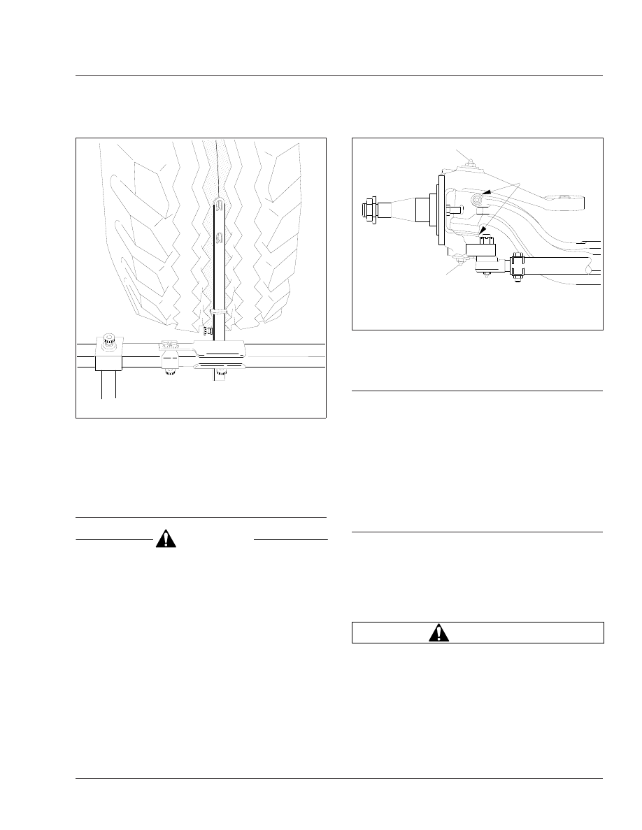
33–05 Knuckle Pin Lubrication,

Dana Spicer Axles

CAUTION

Use regulated pressure when lubricating the
knuckle assemblies, otherwise damage could re-
sult to the knuckle caps.

Park the vehicle on a level surface, apply the parking
brakes, and chock the tires. When lubricating upper
and lower knuckle assemblies, do not raise the front
axle. Wipe the fittings clean, then apply multipurpose
chassis grease, NLGI Grade 1 (6% 12-hydroxy
lithium stearate grease) or NLGI Grade 2 (8% 12-
hydroxy lithium stearate grease), until new grease is
seen at the junctions of the axle beam and knuckles.
See

Fig. 6

Knuckle pins without grease fittings are

permanently lubricated.

33–06 Tie Rod Lubrication,

Dana Spicer Axles

For any Dana Spicer axle that requires lubrication of
the tie-rod ends, wipe the grease fittings clean, then
pump multipurpose chassis grease, NLGI Grade 1
(6% 12-hydroxy lithium stearate grease) or NLGI
Grade 2 (8% 12-hydroxy lithium stearate grease),
into the tie-rod ends until all used grease is forced
out and fresh grease is seen at the ball stud neck.

33–07 Basic Inspection, Meritor

Unitized Wheel Ends

1.

Park the vehicle on a level surface, set the park-
ing brakes, shut down the engine, and chock the
rear tires.

2.

Raise the vehicle until the front tires are clear of
the ground. Support the vehicle with safety
stands.

WARNING

Never work under a vehicle that is supported only
by a jack. Jacks can slip, causing the vehicle to
fall. This could result in serious injury or death.

IMPORTANT: A clicking sound while rotating the
wheel end (hub) is normal and does not indicate
a problem.

f400100a

08/30/94

Fig. 5, Setting Trammel Bar Pointers

11/21/95

f330129

1

1

A

A. Grease Exit
1.

Grease Fitting

Fig. 6, Dana Spicer Knuckle Pin Lubrication

Front Axle

33

33/3

3.

Rotate the tire and hub assembly. They should
rotate smoothly and without noise. Grasp the
brake chamber while rotating the hub to detect
any hub vibration.

If the hub rotates smoothly, go to the next step.

If the tire and hub assembly do not rotate
smoothly, or you hear noise during rotation, go to
"End-Play Check, Meritor Unitized Wheel Ends."

4.

Grasp the tire and hub assembly at the 3 o’clock
and 9 o’clock positions. Using about 50 pounds
(23 kg) of force, check for vertical and horizontal
movement.

5.

If no movement or looseness is detected, raise
the vehicle to remove the safety stands, lower
the vehicle, and remove the chocks from the
tires.

If any movement or looseness is detected, go to
the next step.

6.

Check the wheel-to-hub mounting. Make sure the
wheel and tire assembly is mounted correctly
and that all hardware is secure.

7.

Apply the service brakes to lock the hub and
axle spindle together. Check again for movement
and looseness.

If movement is detected, the king pin or king pin
bushings are probably worn.

If applying the service brake eliminates the
movement, the problem is probably caused by
incorrect wheel bearing end-play. Go to "End-
Play Check, Meritor Unitized Wheel Ends."

33–08 End-Play Check, Meritor

Unitized Wheel Ends

1.

Park the vehicle on a level surface, set the park-
ing brakes, shut down the engine, and chock the
rear tires.

2.

Remove the hub cap.

3.

Raise the vehicle until the front tires clear the
ground. Support the vehicle with safety stands.

WARNING

Never work under a vehicle that is supported only
by a jack. Jacks can slip, causing the vehicle to
fall. This could result in serious injury or death.

4.

Remove the tire and wheel assembly.

NOTE: It is normal for small amounts of grease
to be visible around the inner and outer wheel
bearings.

5.

Remove the brake drum. If needed, back off the
slack adjuster.

6.

Attach the magnetic base of a dial indicator to
the end of the axle spindle.

7.

Touch the dial indicator stem to the surface of
the hub, making sure the stem is perpendicular
to the surface of the hub.

8.

Set the dial indicator to zero.

9.

Without rotating the hub, grasp it at the 3 and 9
o’clock positions, and push it straight in. Note the
reading on the dial indicator.

Pull the hub straight out. Note the reading on the
dial indicator.

The difference between the two measurements is
the end-play.

10. If the end-play is less than 0.003 inch (0.08 mm),

go to the step for installing the hub cap.

If the end-play is 0.003 inch (0.08 mm) or
greater, go to the next step.

11. Remove the outer locknut and tabbed washer

from the axle spindle.

12. Loosen, but don’t remove, the inner locknut.

13. While rotating the hub a minimum of five rota-

tions, tighten the inner locknut 600 lbf·ft (813
N·m).

14. Install the tabbed washer and outer locknut.

Tighten 250 lbf·ft (339 N·m).

15. Repeat the procedure for checking end-play.

16. If end-play is greater than 0.003 inch (0.08 mm)

but less than 0.006 inch (0.15 mm), record it in
the vehicle maintenance log. Go to the next step.

If end-play is 0.006 inch (0.15 mm) or greater,
replace the entire wheel end assembly. For in-
structions, see Group 33 of the Columbia®
Workshop Manual
.

17. Check the rotation of the hub. If it doesn’t rotate

smoothly and without noise, replace the entire
wheel end assembly. For instructions, see Group
33 
of the Columbia® Workshop Manual.

Front Axle

33

33/4

If the hub rotates smoothly and without noise, go
to the next step.

18. Bend an opposing tab of the tabbed washer over

a flat of the outer locknut.

19. Install the wheel and tire assembly. Hand-tighten

the wheel nuts.

20. Raise the vehicle, remove the jackstands, then

lower the vehicle.

21. Tighten the wheel nuts 500 lbf·ft (678 N·m).

22. Install the hub cap.

If installing a metal hub cap, go to the next step.

If installing a plastic hub cap, do the following:

22.1

Apply a continuous 1/8-inch (3-mm) bead
of RTV silicone sealant to the outside first
thread of the hub cap. Apply the sealant
around the entire circumference.

IMPORTANT: Use only the following RTV
sealants on the hub cap:

• Meritor part number 2297-Z-7098
• Three Bond®
• Loctite® Ultra Grey Adhesive Sealant 18581

22.2

Install the hub cap by hand until it is
seated.

NOTE: Disregard the torque value em-
bossed on the hub cap.

22.3

Using a torque wrench, tighten the hub
cap 75 lbf·ft (102 N·m).

If you cannot tighten the hub cap to the
correct torque value, or if it makes a pop-
ping sound while being tightened, replace
it with a new one.

23. If installing a metal hub cap, do the following:

23.1

Using a wire brush, clean the unitized
wheel-end inner threads and the hub cap
external threads.

23.2

Apply Loctite 17430 gasket sealant to the
external hub cap threads.

23.3

Install the hub cap by hand until it is
seated.

23.4

Using a torque wrench, tighten the hub
cap 350 lbf·ft (475 N·m).

NOTE: If you cannot tighten the hub cap to
the correct torque value, or if it makes a
popping sound while being tightened, re-
place it with a new one.

24. Remove the chocks from the tires.

33–09 Kingpin Lubrication,

Detroit

Axles

1.

Park the vehicle on a level surface, shut down
the engine, and set the parking brake. Chock the
tires. When lubricating the kingpin, do not raise
the front axle.

2.

Wipe the fittings clean.

3.

Apply multipurpose chassis grease, NLGI Grade
1 (6% 12-hydroxy lithium stearate grease) or
NLGI Grade 2 (8% 12-hydroxy lithium stearate
grease), until new grease is seen at the junctions
of the axle beam and knuckles. For locations of
grease fittings, see

Fig. 7

for grease exit points,

see

Fig. 8

.

33–10 Tie Rod Lubrication,

Detroit

Axles

For any Detroit axle that requires lubrication of the
tie-rod ends, wipe the grease fittings clean, then
pump multipurpose chassis grease, NLGI Grade 1
(6% 12-hydroxy lithium stearate grease) or NLGI
Grade 2 (8% 12-hydroxy lithium stearate grease),
into the tie-rod ends until all used grease is forced
out and fresh grease is seen at the ball stud neck.
See

Fig. 9

.

Front Axle

33

33/5

06/07/2012

f330272

A

B

1

1

A

Upper View, LH Side

B

Lower View, LH Side

1.

Grease Fitting

Fig. 7, Kingpin Grease Fittings, Detroit Axles

09/13/2012

f330275

Fig. 8, Kingpin Grease Exit Points, Detroit Axles

06/12/2012

f330273

1

2

NOTE: No grease should emit from the tie-rod boot. If
grease emits from the tie-rod boot, the boot is dam-
aged.

1.

Grease Fitting

2.

Boot

Fig. 9, Tie Rod Grease Fitting and Boot, Detroit Axles

Front Axle

33

33/6


Content   ..  16  17  18  19   ..