Freightliner Columbia. Manual - part 6


  Index      Freightliner     Freightliner Columbia - service manual 2015 year


Search            


Content   ..  4  5  6  7   ..


Freightliner Columbia. Manual - part 6


Safety Precautions

DANGER

When working on the vehicle, shut down the en-
gine, set the parking brake, and chock the tires.
Before working under the vehicle, always place
jack stands under the frame rails to ensure the
vehicle can not drop. Failure to follow these steps
could result in serious personal injury or death.

01–01 Engine Support

Fasteners Check

Front and rear engine supports for vehicles built from
January 2007 require no periodic maintenance.
Mounts should be inspected when the engine is re-
moved for service. For vehicles manufactured prior to
January 2007, perform the following check.

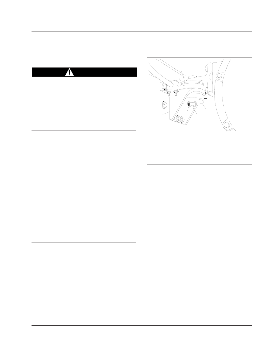
Check the rear engine support fasteners (see

Fig. 1

,

Ref. 4) for tightness. Tighten the 3/4-inch fasteners
215 to 265 lbf·ft (292 to 359 N·m).

Check the front engine support fasteners for tight-
ness. Tighten the 5/8-inch fasteners 125 lbf·ft (170
N·m).

NOTE: At engine overhaul, and whenever the
engine has been removed, inspect the lower
and upper isolators (Refs. 1 and 6), and replace
them if they are worn. See Group 01 of the
Columbia® Workshop Manual for procedures.

01–02 Engine Drive Belt

Inspection

Worn or loose drive belts may cause premature
bearing failure or engine overheating. Excessive ten-
sion, or too little tension on the belt may result in ex-
cessive and premature belt wear. Poly-V belts, or
serpentine belts, are retained by a belt tensioner that
requires no tension adjustment. Replace the drive
belt if any conditions described in "Visual Inspection"
are found. V-belts are installed as individual belts,
and as matched sets. When replacing matched sets
of belts, always replace both belts at the same time.
Matched belts must be from the same manufacturer.
To inspect a belt, gently twist it to view the belt side-

walls and bottom. Inspect all belts for the following
conditions, then perform the "Belt Tension Inspec-
tion."

Visual Inspection

1.

Inspect the belt for glazing. See

Fig. 2

, Ref. A.

Glazing is represented by shiny sidewalls, and is
caused by friction created when a loose belt slips
in the pulleys. It can also be caused by oil or
grease on the pulleys.

2.

Check the belt for ply separation. See

Fig. 2

,

Ref. B. Oil, grease, or belt dressing can cause
the belt to fall apart in layers. Repair any oil or
coolant leaks that are affecting the belts before
replacing the drive belts. Do not use belt dress-
ing on any belt.

3.

Check the belt for a jagged or streaked sidewall.
See

Fig. 2

Ref. C. Jagged or streaked sidewalls

are the result of foreign objects, such as sand or
gravel in the pulley, or a rough pulley surface.

4.

Check for tensile breaks (breaks in the cord
body). See

Fig. 2

Ref. D. Cuts in a belt are usu-

ally caused by foreign objects in the pulley, or by
prying or forcing the belt during removal or instal-
lation.

f220047a  

1  

2  

3  

4  

5  

6  

2  

10/05/94 

1.

Lower Isolator

2.

Engine Support Washer

3.

3/4–10 Capscrew

4.

3/4–10 Hexnut

5.

Engine Mount

6.

Upper Isolator

Fig. 1, Engine Rear Mount

Engine

01

01/1

5.

Check for uneven ribs on serpentine (poly-V)
belts. See

Fig. 2

Ref. E. Foreign objects in the

pulley will erode the undercord ribs, causing the
belt to lose its gripping power.

6.

Check the drive belts for cracks. See

Fig. 2

Ref.

F. Small irregular cracks are usually signs of an
old belt.

7.

Inspect the pulleys for excessive play or wobble.
Excessive play or wobble indicates a failure of
the pulley bearing. Check for belt squealing or
squeaking. Replace the bearings as necessary.

NOTE: If it is difficult to distinguish the location
of a supposed bearing noise, place a stetho-
scope on the component being checked, not the
pulley, to isolate the area from outside interfer-
ence.

8.

Inspect all pulleys for foreign objects, oil, or
grease in the grooves.

Belt Tension Inspection

Threaded-Adjustment Type

1.

Apply the parking brakes and chock the tires.

2.

Install a belt tension gauge at the center of the
belt’s longest free-span. Check belt tension. See

Table 1

for belt tension specifications.

3.

If belt tension is not correct, see Group 01 of the
Columbia® Workshop Manual to adjust belt ten-
sion.

Drive Belt Tensions

Engine

Component

Belt Tension: lbf (kg)

Cummins ISB, ISC, ISM

Refrigerant Compressor

100 (45)

f150010a

A

B

C

D

E

F

11/21/94

A. Glazing
B. Separating Layers

C. Streaked Sidewalls
D. Tensile Break

E. Uneven Ribs
F.

Cracks

Fig. 2, Drive Belt Replacement Conditions

Engine

01

01/2

Drive Belt Tensions

Engine

Component

Belt Tension: lbf (kg)

Mercedes-Benz MBE900

Fan and Alternator

29.5 (27.9)

Refrigerant Compressor

30.0 (28.4)

Table 1, Drive Belt Tensions

Spring-Tension Type

On belts equipped with a spring tensioner, belt ten-
sion is automatically adjusted. Check that the ten-
sioner is holding tension on the belt by inserting the
end of a breaker bar in the 1/2-inch square hole on
the forward face of the tensioner, and rotating the
tensioner away from the belt. When the breaker bar
is slowly released, the tensioner should return to its
original position. The tensioner should rotate
smoothly with no binding. If not, see Group 01 of the
Columbia® Workshop Manual for replacement in-
structions.

NOTE: The following engines, which appear in

Table 1

are provided with automatic tensioners

for the fan and alternator belts.

01–03 Pacbrake Inspection and

Lubrication

With frequent use, the Pacbrake Exhaust Brake will
operate maintenance-free. If the vehicle is used in-
consistently or seasonally, it will be necessary to per-
form preventative maintenance. If the vehicle is ex-
posed to excess moisture, or is used only for
periodic or seasonal use, perform the following steps:

1.

With the engine off, use any oil-free or non-
petroleum-based high-heat lubricant, and spray
or coat a sufficient amount on the restrictor valve
shaft and the attaching locations at each end of
the actuation cylinder.

2.

With your hands or a pair of pliers, motion the
valve several times to distribute the lubricant
down the shaft and the attaching locations.

NOTE: Operation of the Pacbrake could be af-
fected by starting the engine and idling for short
periods of time. During a cold engine start-up,
moisture occurs in the engine and the exhaust
system that creates a corrosion hazard. The
brake housing may trap water in the valve shaft

bore causing corrosion, resulting in an improp-
erly functioning or non-functioning brake. If it is
necessary to periodically start the engine, attain
normal operating temperatures before shutting
down the engine.

Engine

01

01/3

Title of Maintenance Operation (MOP)

MOP Number

Air Cleaner Element Inspection and Replacement . . . . . . . . . . . . . . . . . . . . . . . . . . . . . . . . . . . . . . . . . . 09–01

Air Intake

09

Index, Alphabetical

Columbia Maintenance Manual, November 2014


Content   ..  4  5  6  7   ..