Ford Festiva. Instruction - part 81


  Index      Ford     Ford Festiva - service and repair instruction 1991 year


Search            


Content   ..  79  80  81  82   ..


Ford Festiva. Instruction - part 81


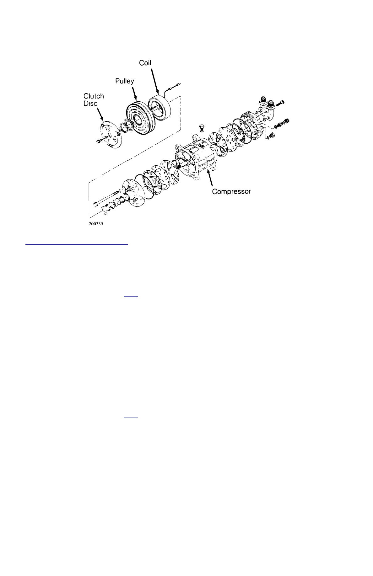
Fig. 5: Diesel Kiki 6-Cylinder Compressor


Courtesy of MITSUBISHI MOTOR SALES OF AMERICA. 

FORD FX-15 CLUTCH R & I 

Removal 

1. Using Clutch Holder (00 41 0812 05), remove clutch plate retaining bolt and discard. Using an 8 mm bolt threaded into clutch plate, 

remove clutch plate and shim(s). See 

Fig. 6

 .  

2. Remove snap ring and pulley assembly. Install Shaft Protector (49 UN01 47) over shaft seal opening. Use a 2-jaw puller to remove 

clutch coil from compressor.  

Installation 

1. Ensure clutch coil mounting surface is clean. Use Coil Installer (49 UN01 046) and 2-jaw puller engaged to rear side of compressor 

front mounts to press coil into place.  

2. Install pulley assembly. Install pulley assembly snap ring with bevel side of snap ring facing out. Install shim(s) and clutch plate. Install 

a NEW clutch plate retaining bolt and tighten to 96-120 INCH lbs. (11-14 N.m).  

3. Use a feeler gauge to check clearance between clutch plate and pulley assembly. Clearance should be .018-.033" (.46-.84 mm). If 

clearance is incorrect, add or remove shims as necessary.  

FORD FX-15 SHAFT SEAL R & I 

Removal 

1. Using Clutch Holder (000 41 0812 05), remove clutch plate retaining bolt and discard. Using an 8 mm bolt threaded into clutch plate, 

remove clutch plate and shim(s). See 

Fig. 6

 .  

2. Remove shaft felt seal. Thoroughly clean seal area of compressor. Remove shaft seal retaining snap ring. Position Shaft Seal Remover 

(49 UN01 044) over compressor shaft.  

3. Push shaft seal remover downward against seal. Ensure end of shaft seal remover is engaged with inside of seal. Rotate shaft seal 

remover clockwise to expand remover tip inside seal. Pull shaft seal from compressor.  

Installation 

1. Lubricate shaft seal protector and shaft seal with refrigerant oil. Install shaft seal on shaft seal protector so lip seal is toward compressor 

(large end of shaft seal protector).  

2. Install shaft seal protector on compressor shaft. Using shaft seal installer (49 UN01 043), push shaft seal down seal protector until seal 

is seated.  

3. Remove shaft seal installer and protector. Install a NEW shaft seal retaining snap ring and shaft seal felt. Install shim(s) and clutch plate. 

Install a NEW clutch plate retaining bolt and tighten to 91-120 INCH lbs. (11-14 N.m).  

4. Use a feeler gauge to check clearance between clutch plate and pulley assembly. Clearance should be .018-.033" (.46-.84 mm). If 

clearance is incorrect, add or remove shims as necessary.  


Fig. 6: Exploded View of Compressor Clutch (Ford FX-15)


Courtesy of MAZDA MOTORS CORP. 

HARRISON R4 4-CYL CLUTCH R & I 

Removal 

1. Clamp Holding Fixture (J-25008-A) in a vise and attach compressor to holding fixture with thumb screws. Use Clutch Hub Holder (J-

33027) to hold clutch. Remove shaft nut using Shaft Nut Socket (J-9399).  

2. Thread Clutch Plate and Hub Assembly Remover (J-33013-B) into hub. Hold body of remover with a wrench and turn center screw into 

remover body to remove clutch plate and hub assembly. Remove shaft key and retain for assembly. See 

Fig. 5

 .  

Installation 

1. Install shaft key into hub key groove. Allow key to project approximately 1/8" out of key way. Shaft key is curved slightly to provide an 

interference fit in hub key groove.  

2. Ensure frictional surface of clutch plate and clutch rotor are clean before installing clutch plate and hub assembly. Align shaft key with 

shaft key way and place clutch plate and hub assembly onto compressor shaft.  

3. Hold hex portion of Installer (J-9480-B) with a wrench. Tighten center screw to press hub into shaft until there is .020-.040" (.5-1.0 

mm) air gap between frictional plate and clutch rotor.  

4. Install new shaft nut with small diameter boss of nut against crankshaft shoulder. Use Thin Wall Socket (J-9399) and Clutch Hub 

Holder (J-25030). Tighten shaft nut to 10 ft. lbs. (14 N.m). Spin pulley rotor by hand to ensure rotor is not rubbing on clutch drive 
plate.  

HARRISON R4 4-CYL SHAFT SEAL R & I 

Removal 

1. Clamp Holding Fixture (J-25008-A) in a vise and attach compressor to holding fixture with thumb screws. Use Clutch Hub Holder (J-

33027) to hold clutch. Remove shaft nut using Shaft Nut Socket (J-9399).  

2. Thread Clutch Plate and Hub Assembly Remover (J-33013-B) into hub. Hold body of remover with a wrench and turn center screw into 

remover body to remove clutch plate and hub assembly. Remove clutch plate and shaft key. Pry out dust seal (if equipped). Remove seal 
seat snap ring. Thoroughly clean compressor neck area and "O" ring groove surrounding shaft. Any dirt or foreign material may cause 
compressor damage.  

3. Use Seal Remover/Installer (J23128-A), remove seal with a twisting motion. Use "O" Ring Remover (J-9553-01) to remove "O" ring.  

Installation 

1. Coat new shaft seal with refrigerant oil and install shaft seal on remover/installer. Align compressor shaft machined surface with shaft 

seal and install. Turn remover/installer slightly counterclockwise to secure shaft seal tangs.  

2. Using Seal Installer (J-33011), install "O" ring and coat with refrigerant oil. Coat seal seat with refrigerant oil and install using seal seat 

remover/installer. Install snap ring. Install dust seal (if supplied in seal kit). See 

Fig. 7

 .  

NOTE:

DO NOT drive or pound on clutch hub or shaft.


Fig. 7: Harrison R-4 Radial Compressor


Courtesy of ISUZU MOTOR CO. 

HARRISON V5 5-CYLINDER CLUTCH R & I 

Removal 

1. Clamp Holding Fixture (J-34992) in vise and attach compressor to holding fixture with thumb screws. Use Clutch Hub Holder (J-33027) 

to hold clutch. Remove shaft nut using Shaft Nut Socket J-33022).  

2. Thread Clutch Plate and Hub Assembly Remover (J-33013-B) into hub. Hold body of remover with a wrench and turn center screw into 

remover body to remove clutch plate and hub assembly. Remove shaft key and retain for installation.  

Installation 

1. Install shaft key into hub key groove. Allow key to project approximately 1/8" (3.2 mm) out of key way. Shaft key is curved slightly to 

provide an interference fit in hub key groove.  

2. Ensure frictional surface of clutch plate and clutch rotor are clean before installing clutch plate and hub assembly. Align shaft key with 

shaft key way and place clutch plate and hub assembly onto compressor shaft. 

3. Hold hex portion of installer (J-33013) with a wrench. Tighten center screw to press hub into shaft until there is .015-.025" (.38-.64 

mm) air gap between frictional plate and clutch rotor.  

4. Install new shaft nut with a small diameter boss of nut against crankshaft shoulder. Use Thin Wall Socket (J-9399) and Clutch Hub 

Holder (J-25030). Tighten shaft nut to 96-192 INCH lbs. 11-22 N.m). Spin pulley rotor by hand to ensure rotor is not rubbing on clutch 
drive plate. See 

Fig. 8

 .  

HARRISON V5 5-CYLINDER SHAFT SEAL R & I 

Removal 

Discharge refrigerant from system using approved refrigerant recovery/recycling equipment. See SERVICING PRECAUTIONS at beginning of 
article. Remove clutch plate assembly. Remove shaft seal snap ring. Thoroughly clean inside of compressor neck area around shaft and seal. 
Engage tangs of Seal Remover/Installer (J-23128-A) into recessed portion of seal and remove seal. Remove and discard seal "O" ring from 
compressor neck. Thoroughly clean inside of compressor neck and "O" ring groove. 

Installation 

1. Coat new "O" ring with refrigerant oil and install on "O" ring installer (J-33011). Install "O" ring into groove in compressor neck. Attach 

new seal to Seal Remover/Installer (J-23128-A). Dip seal in clean refrigerant oil.  

2. Place Seal Protector (J-34614) over compressor shaft. Push new seal over shaft protector. Install new snap ring with flat side against 

seal. Install clutch plate assembly.  

NOTE:

DO NOT drive or pound on clutch hub or compressor shaft, as compressor could be damaged 
internally.


Fig. 8: Exploded View of Harrison V5 5-Cylinder Compressor


Courtesy of GENERAL MOTORS CO. 

HITACHI 5 & 6-CYL CLUTCH R & I 

Removal 

1. Using Clutch Holder (KV99412302), hold clutch hub. Remove shaft nut from shaft. Using Clutch Hub Remover (KV994C5780), 

remove clutch hub.  

2. Pry inner snap ring off. Remove pulley and bearing assembly. If assembly cannot be removed by hand, use Pulley and Bearing Removers 

(KV994C5781 and KV994C5782).  

3. Remove clamping screws that secure coil assembly leads. Remove inner snap ring from coil assembly. Remove coil assembly from front 

cover. See 

Fig. 9

 .  

Inspection 

Check friction surfaces of clutch for damage due to excessive heat, or excessive grooving due to slippage. Replace compressor components as 
necessary. Oil or dirt on friction surfaces should be cleaned with a solvent and a dry rag. Check coil for binding, shorted or open leads. 

Installation 

1. Install coil assembly on compressor. Properly position terminals. Using snap ring pliers, install snap ring. Using a plastic mallet, drive 

pulley and bearing assembly onto neck of front cover. Turn pulley, making sure that there is no noise and that rotation is free. Ensure 
there is no pulley play.  

2. Using snap ring pliers, install inner snap ring. Remove all oil from clutch pulley. Fit key and clutch hub to shaft. Select adjusting spacer 

which gives the correct clearance between pulley and clutch hub.  

3. Coat shaft nut with Loctite and install. Using a feeler gauge, measure clutch hub-to-pulley clearance. Clearance should be .020-

.031" (.5-.8 mm). If specified clearance is not obtained, replace adjusting spacer and readjust.  

4. When replacing compressor clutch assembly, DO NOT forget break-in operation. This is accomplished by engaging and disengaging 

clutch 30 times.  


Content   ..  79  80  81  82   ..