Ford Festiva. Instruction - part 72
The voltage controlled driver inside the computer operates much like a simple switch because it does not need to worry about limiting current
flow. Recall, this driver typically requires injector circuits with a total leg resistance of 12 or more ohms.
The driver is either ON, closing/completing the circuit (eliminating the voltage-drop), or OFF, opening the circuit (causing a total voltage
drop).
Some manufacturers call it a "saturated switch" driver. This is because when switched ON, the driver allows the magnetic field in the injector
to build to saturation. This is the same "saturation" property that you are familiar with for an ignition coil.
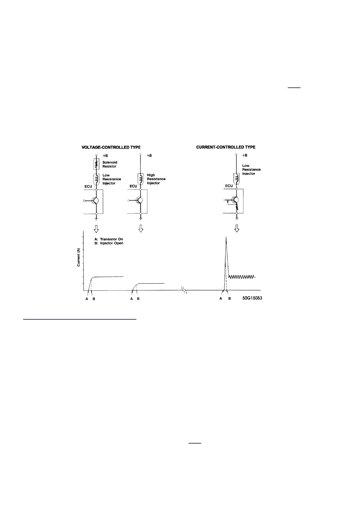
There are two ways "high" resistance can be built into an injector circuit to limit current flow. One method uses an external solenoid resistor
and a low resistance injector, while the other uses a high resistance injector without the solenoid resistor. See the left side of Fig.
Fig. 1
.
In terms of injection opening time, the external resistor voltage controlled circuit is somewhat faster than the voltage controlled high resistance
injector circuit. The trend, however, seems to be moving toward use of this latter type of circuit due to its lower cost and reliability. The ECU
can compensate for slower opening times by increasing injector pulse width accordingly.
Fig. 1: Injector Driver Types - Current and Voltage
CURRENT CONTROLLED CIRCUIT ("PEAK & HOLD")
The current controlled driver inside the computer is more complex than a voltage controlled driver because as the name implies, it has to limit
current flow in addition to its ON-OFF switching function. Recall, this driver typically requires injector circuits with a total leg resistance of
less than 12 ohms.
Once the driver is turned ON, it will not limit current flow until enough time has passed for the injector pintle to open. This period is preset by
the particular manufacturer/system based on the amount of current flow needed to open their injector. This is typically between two and six
amps. Some manufacturers refer to this as the "peak" time, referring to the fact that current flow is allowed to "peak" (to open the injector).
Once the injector pintle is open, the amp flow is considerably reduced for the rest of the pulse duration to protect the injector from
overheating. This is okay because very little amperage is needed to hold the injector open, typically in the area of one amp or less. Some
manufacturers refer to this as the "hold" time, meaning that just enough current is allowed through the circuit to "hold" the already-open
injector open.
There are a couple methods of reducing the current. The most common trims back the available voltage for the circuit, similar to turning down
a light at home with a dimmer.
The other method involves repeatedly cycling the circuit ON-OFF. It does this so fast that the magnetic field never collapses and the pintle
stays open, but the current is still significantly reduced. See the right side of Fig.
Fig. 1
for an illustration.
The advantage to the current controlled driver circuit is the short time period from when the driver transistor goes ON to when the injector
actually opens. This is a function of the speed with which current flow reaches its peak due to the low circuit resistance. Also, the injector
closes faster when the driver turns OFF because of the lower holding current.
THE TWO WAYS INJECTOR CIRCUITS ARE WIRED
NOTE:
Never apply battery voltage directly across a low resistance injector. This will cause injector damage
from solenoid coil overheating.
NOTE:
Never apply battery voltage directly across a low resistance injector. This will cause injector damage
from solenoid coil overheating.