Ford Festiva. Instruction - part 46
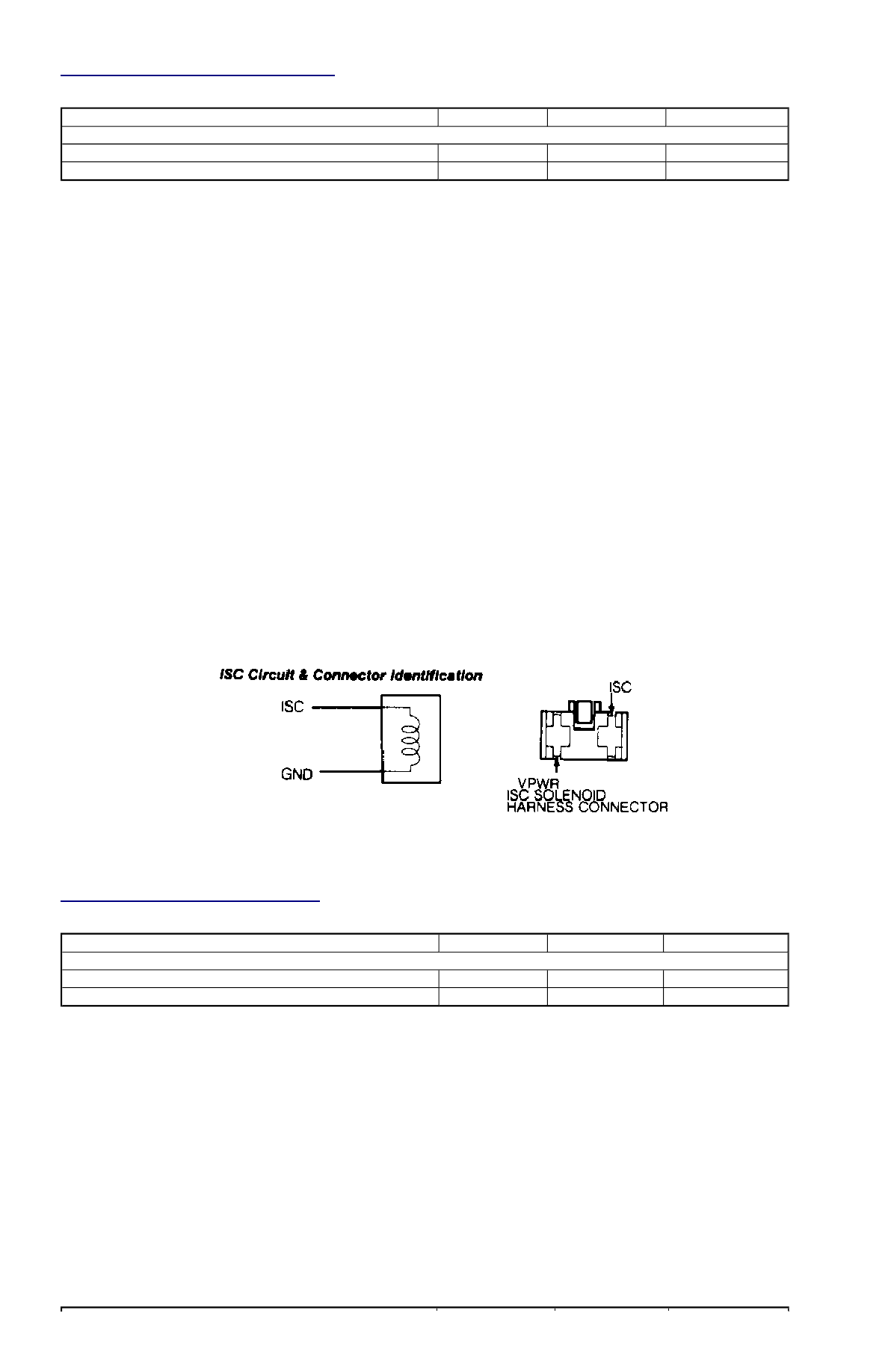
Fig. 14: Identifying CANP Circuit & Connector
CANP CIRCUIT PIN IDENTIFICATION
1. Turn ignition off. Install BOB. Leave ECA disconnected. Turn ignition on. Remove canister purge hose from intake manifold, and apply
vacuum. Connect a jumper wire between CANP test terminal and ground. If vacuum releases, solenoid is okay. If vacuum does not
release, go to next step.
2. Locate CANP solenoid near center of cowl panel. Unplug solenoid connector. Apply vacuum to port from engine vacuum source.
Replace CANP solenoid if it does not hold vacuum.
3. Connect BOB. Leave ECA disconnected. Reconnect wiring to CANP solenoid. Turn ignition on. Apply vacuum to CANP solenoid.
Connect jumper wire between CANP test pin on BOB and ground. If vacuum drops to zero, solenoid function is okay. Return to QUICK
TESTS if sent here from there. If vacuum does not drop to zero, go to next step.
4. Turn ignition off. Unplug CANP solenoid connector. Turn ignition on. Measure voltage between VPWR wire on harness connector and
ground. If voltage is not higher than 10 volts, repair VPWR wire to main relay. If voltage is higher than 10 volts, go to next step.
5. Turn ignition off. Unplug CANP solenoid connector. Turn ignition on. Measure voltage between solenoid connector VPWR wire and
solenoid connector SIG wire. Connect jumper wire between CANP test pin on BOB and ground. If voltage is higher than 10 volts only
when solenoid is activated, replace solenoid. If voltage is not higher than 10 volts only when solenoid is activated, go to next step.
6. Turn ignition off. Connect BOB. Leave ECA disconnected. Unplug CANP solenoid connector. Measure resistance between SIG test pin
and solenoid connector SIG wire. If resistance is not less than 5 ohms, repair SIG wire to ECA. If resistance is less than 5 ohms, go to
next step.
7. Turn ignition off. Connect BOB. Leave ECA disconnected. Unplug solenoid connector. Measure resistance between SIG test pin and all
other test pins. If resistance between SIG PRC test pin and any other pin is less than 5 ohms, repair CANP wire to ECA. If resistance
between CANP test pin and all other pins is greater than 10,000 ohms, replace ECA.
PINPOINT TEST ISC - IDLE SPEED CONTROL
Fig. 15: Identifying ISC Circuit & Connector
ISC CIRCUIT PIN IDENTIFICATION
1. Install BOB, leaving ECA disconnected. Turn ignition on. Connect a jumper between BOB test pin No. 41 and ground. Listen for
clicking sound from solenoid, mounted on throttle body. If clicking sound occurs, ISC solenoid is okay; return to QUICK TESTS if sent
here from there. If no clicking sound occurs, go to next step.
2. Unplug ISC solenoid connector. With ignition on, measure voltage between VPWR wire and ground. If voltage is less than 10 volts,
repair VPWR wire to main relay. Go to next step if voltage is not less than 10 volts.
3. Measure voltage between ISC solenoid VPWR wire and solenoid connector SIG wire while cranking engine. Replace solenoid if voltage
is more than 10 volts only when engine is cranking. If okay, go to next step.
4. With BOB installed and ECA disconnected, unplug ISC solenoid connector. Check for continuity between BOB SIG test pin and ISC
connector SIG wire. If resistance is not less than 5 ohms, repair ISC wire between solenoid and ECA. If okay, go to next step.
5. With BOB installed and ECA disconnected, measure resistance between BOB SIG test pin and all other test pins. If resistance is less
than 5 ohms, repair short in SIC wire to ECA. If resistance is not less than 5 ohms, replace ECA.
PINPOINT TEST STI - SELF-TEST INPUT
STI CIRCUIT PIN IDENTIFICATION
Circuit
ECA Pin
BOB Pin
Wire Color
CANP
1.3L
2X
31
RED
1.6L
2P
32
YEL
NOTE:
Enter this test only when a Code 34 is displayed during QUICK TESTS procedure or when directed here
from another PINPOINT TEST.
Circuit
ECA Pin
BOB Pin
Wire Color
ISC
1.3L
2W
41
RED/BLK
1.6L
2Q
41
GRN
NOTE:
Enter this test only when sent here from QUICK TESTS.