Ford Festiva. Instruction - part 39


  Index      Ford     Ford Festiva - service and repair instruction 1991 year


Search            


Content   ..  37  38  39  40   ..


Ford Festiva. Instruction - part 39


VALVE CLEARANCE 

IGNITION SYSTEM 

IGNITION COIL 

IGNITION COIL RESISTANCE 

CRANKSHAFT POSITION SENSOR 

CRANKSHAFT POSITION SENSOR RESISTANCE 

HIGH TENSION WIRE RESISTANCE 

HIGH TENSION WIRE RESISTANCE 

SPARK PLUGS 

SPARK PLUG TYPE 

SPARK PLUG SPECIFICATIONS 

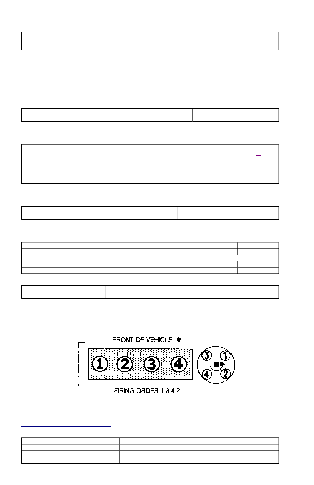
FIRING ORDER & TIMING MARKS 


Fig. 1: Firing Order & Distributor Rotation


IGNITION TIMING 

(1)

Information is not available.

(2)

Lowest cylinder compression reading should not be less than 75 percent of highest cylinder compression reading.

NOTE:

All models are equipped with hydraulic lash adjusters. No adjustments are required.

Application

Primary (Ohms)

Secondary (Ohms)

1.3L & 1.6L

0.8-1.6

6000-30,000

Application

Ohms

1.3L

(1)

 210-250

1.6L

(2)

(1)

Measured between CPS (Yellow/Blue) and GND terminal.

(2)

Capri is equipped with Cylinder Identification (CID) sensor. Resistance is not specified.

Application

Ohms

Coil Wire & Spark Plug Wires

4000-6000 per foot

Application

Motorcraft

1.3L

AGS32C

1.6L

Non-Turbo

AGSP32C

Turbo

AGS32C

Application

Gap: In.- (mm)

Torque: Ft.-Lbs./(N.m)

1.3L & 1.6L

.039-.043 (1.0-1.1)

10-17 (14-23)

Application

Auto. Trans.

Man. Trans.

1.3L

9-11 @ 850

9-11 @ 700

1.6L Non-Turbo

1-3 @ 850

0-4 @ 850

1.6L Turbo

10-14 @ 850

0-4 @ 850

FUEL SYSTEM 

FUEL PUMP 

FUEL PUMP PERFORMANCE 

INJECTOR RESISTANCE 

FUEL INJECTOR RESISTANCE 

IDLE SPEED 

IDLE SPEED 

(1)


THROTTLE POSITION SWITCH (TPS) 

TPS ADJUSTMENT 

NOTE:

For fuel pressure specifications, see 

FUEL PRESSURE SPECIFICATIONS

 article.

NOTE:

Fuel pump performance is a measurement of fuel pressure and volume availability, not regulated fuel 
pressure.

Application

Pressure -psi kg/cm

2

 )

Min. Vol. in 10 sec. oz. (CC)

1.3L

(1)


7.4 (220)

1.6L

(1)


5.5 (167)

(1)

For fuel pressure specifications, see 

FUEL PRESSURE SPECIFICATIONS

 article.

Application

Ohms

1.3L & 1.6L

12-16

Application

Auto. Trans.

Man. Trans.

1.3L

830-870

680-720

1.6L

800-900

800-900

(1)

With jumper wire connected between single-wire STI terminal and ground.

NOTE:

Capri is equipped with throttle position sensor. No adjustment is required.

Test Condition 

(1)


Cont. Between IDL-TL

Cont. Between PSW-TL

.02" (.5 mm)

Yes

No

.03" (.7 mm)

No

No

Wide Open Throttle

No

Yes

(1)

Insert specified feeler gauge between throttle adjustment screw and stop lever.

Copyright 2009 Mitchell Repair Information Company, LLC.  All Rights Reserved. 


Article GUID: A00022695 

Back To Article


F - BASIC TESTING

1991-92 ENGINE PERFORMANCE Ford Motor Co. Basic Diagnostic Procedures 

INTRODUCTION 

The following diagnostic steps help prevent overlooking simple problems and begin diagnosis for a no-start condition. 

The first step in diagnosing any driveability problem is to verify the complaint. Test drive the vehicle under the conditions in which the 
problem reportedly occurred. 

Before entering self-diagnostics, perform a careful and complete visual inspection. Most engine control problems result from mechanical 
breakdowns, poor electrical connections or damaged/misrouted vacuum hoses. Before condemning the computerized system, perform each test 
listed in this article. 

PRELIMINARY INSPECTION & ADJUSTMENTS 

VISUAL INSPECTION 

Perform a visual inspection of all electrical wiring. Look for chafed, stretched, cut or pinched wiring. Ensure electrical connections fit tightly 
and are not corroded. Ensure vacuum hoses are properly routed and are not cut or pinched. If necessary, see VACUUM DIAGRAMS article in 
the ENGINE PERFORMANCE Section to verify routing and connections. Inspect air induction system for possible vacuum leaks. 

MECHANICAL INSPECTION 

Compression 

Engine mechanical condition can be checked using a compression gauge, vacuum gauge or engine analyzer. See engine analyzer instruction 
instruction for specific instructions. Lowest compression reading must be not less than 75 percent of highest reading. 

Exhaust System Backpressure 

Exhaust system can be checked with a vacuum gauge or a 0-5 psi pressure gauge. If a pressure gauge is used, remove O2 sensor. Connect gauge 
to O2 sensor port. Start engine, and run at 2500 RPM. If exhaust system backpressure is more than 2 psi, exhaust system or catalytic converter 
is plugged. 

If a vacuum gauge is used, connect it to intake manifold vacuum. Start engine. Observe vacuum gauge. Open throttle part way and hold steady. 
If vacuum gauge drops slowly after stabilizing, check exhaust system for a restriction. 

FUEL PRESSURE 

Fuel Pressure Release 

Start engine (if possible), and unplug VAF meter connector. When engine stalls, turn ignition off and reconnect VAF meter wiring. Using shop 
towel, cover fitting to absorb leakage when opening fuel system. 

Fuel Pressure Check 

1. Connect fuel pressure gauge between fuel filter and fuel rail. Open main valve, and close drain valve. Locate fuel pump check connector 

in engine compartment, near left strut. Connect jumper wire between fuel pump test terminals (Black and Green/White wires on Capri 
or Black and Green/Red wires on Festiva).  

2. Turn ignition on to activate fuel pump. If pump does not run, check fuel pump circuit. If possible, start engine. Measure and record fuel 

pressure. For fuel pressure specifications, see 

FUEL PRESSURE SPECIFICATIONS

 article. Disconnect vacuum from pressure 

regulator. Turn engine off. Wait 5 minutes and ensure residual pressure is at least 21 psi (1.5 kg/cm

2

 ).  

3. Operate fuel pump by reconnecting jumper wire at fuel pump check connector. Check fuel pump performance. Pinch hose between 

pressure gauge and fuel filter. Do not hold longer than necessary to check pressure.For fuel pressure specifications, see 

FUEL 

PRESSURE SPECIFICATIONS

 article. If pump does not meet specifications, check fuel pump circuit, fuel pump, fuel tank and fuel 

filter or replace fuel pump.  

FUEL PUMP PERFORMANCE 

NOTE:

Unless stated otherwise in test procedure, perform all voltage tests with a Digital Volt-Ohmmeter 
(DVOM) with a minimum 10-megohm input impedance.

CAUTION:

DO NOT use ignition switch during compression tests on fuel injected vehicles. Fuel injectors are 
triggered by ignition switch during cranking mode. Use a remote starter to crank engine to prevent fire 
hazard and catalytic converter and engine oiling system contamination.

WARNING:

ALWAYS relieve fuel pressure before disconnecting any fuel injection system component. DO NOT 
allow fuel to contact engine or electrical components.

NOTE:

For 1991 fuel pressure specifications, see 

FUEL PRESSURE SPECIFICATIONS

 article. For 1992 fuel 

pressure specifications, see 

FUEL PRESSURE SPECIFICATIONS

 article.

Application

Pressure psi (kg/cm

2

 )

Min. Vol. in 10 sec. Ozs. (cc)

Capri

(1)


5.5 (167)

Festiva

(1)


7.4 (220)

Fuel Pump Circuit 

1. Turn ignition on. Connect jumper wire between fuel pump test connector terminals. See 

Fig. 1

 or 

Fig. 2

 . Turn ignition on to activate 

fuel pump.  

2. Listen for fuel pump sound. If there is no sound, check main fuse, inertia switch (located at left rear shock tower), fuel pump relay, fuel 

pump and all electrical connections.  


Fig. 1: Festiva Fuel System Electrical Schematic


Courtesy of FORD MOTOR CO. 

(1)

For 1991 fuel pressure specifications, see 

FUEL PRESSURE SPECIFICATIONS

 article. For 1992 fuel pressure specifications, 

see 

FUEL PRESSURE SPECIFICATIONS

 article.


Content   ..  37  38  39  40   ..