Ford Festiva. Instruction - part 13


  Index      Ford     Ford Festiva - service and repair instruction 1991 year


Search            


Content   ..  11  12  13  14   ..


Ford Festiva. Instruction - part 13


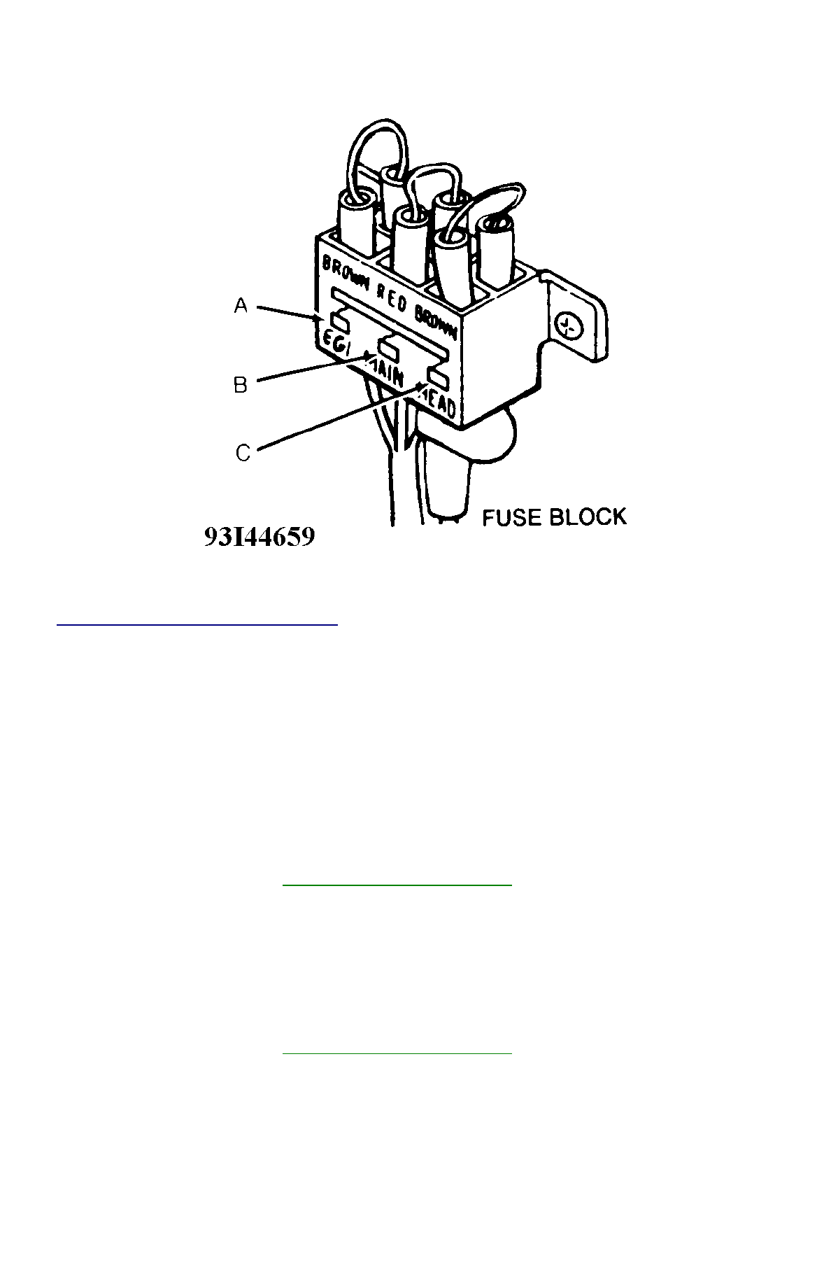
Fig. 2: Underhood Fusible Link Block Identification


Courtesy of FORD MOTOR CO. 

Fusible Link Identification 

A - Brown (PTC) (1988-89 Carburetor) EFE Carburetor Heater  

A - Brown (EGI) (1989-93 EFI) EFI System (1989-92), EGI-EFI System (1993)  

B - Red (Main) Back-Up, Interior & Parking Lights, Brakelights, Taillights, Horn, Luggage Compartment Light, Turn Signal & Hazard 
Flasher Lights, Cluster & Warning Lights, Radio, Cigarette Lighter, Charging & Emission Control Systems, Wiper/Washer Systems, 
A/C-Heater System, Cooling Fan System, Rear Window Defroster, Ignition & Starting Systems, Shift Lock System, Remote Control 
Mirror, Ignition Key Reminder, Passive Restraint System (1990-93)  

C - Brown (Head) Headlights, Daytime Running Lights, Starting & Charging System  

BATTERY SPECIFICATIONS 

All 1988-92 models use a BX-35 battery. The 1993 Festiva uses a 50D 20L standard battery. 

CAUTIONS & WARNINGS 

BATTERY WARNING 

REPLACING BLOWN FUSES 

Before replacing a blown fuse, remove ignition key, turn off all lights and accessories to avoid damaging the electrical system. Be sure to use 
fuse with the correct indicated amperage rating. The use of an incorrect amperage rating fuse may result in a dangerous electrical system 
overload. 

BRAKE PAD WEAR INDICATOR 

Indicator will cause a squealing or scraping noise, warning that brake pads need replacement. 

CAUTION:

When battery is disconnected, vehicles equipped with computers may lose memory data. When battery 
power is restored, driveability problems may exist on some vehicles. These vehicles may require a 
relearn procedure. See 

COMPUTER RELEARN PROCEDURES

 article in the GENERAL INFORMATION 

section.

WARNING:

When battery is disconnected, vehicles equipped with computers may lose memory data. When battery 
power is restored, driveability problems may exist on some vehicles. These vehicles may require a 
relearn procedure. See 

COMPUTER RELEARN PROCEDURES

 article in GENERAL INFORMATION 

section.

CATALYTIC CONVERTER 

Continued operation of vehicle with a severe malfunction could cause converter to overheat, resulting in possible damage to converter and 
vehicle. 

Any modification to the exhaust system on turbo models, which reduces exhaust backpressure, will lead to lean fuel mixtures and excessive 
spark advance. This could cause serious engine damage. 

ELECTROSTATIC DISCHARGE SENSITIVE (ESD) PARTS 

ENGINE OIL 

FUEL PUMP SHUTOFF SWITCH 

This switch stops flow of fuel to engine after a collision. The impact does not have to be great for switch to be triggered. Switch must be reset 
after collision. Switch is located under left rear speaker in luggage compartment. Press button to reset switch. 

FUEL SYSTEM SERVICE 

HALOGEN BULBS 

PASSIVE RESTRAINTS 

RADIATOR CAP 

RADIATOR FAN 

WARNING:

Many solid state electrical components can be damaged by static electricity (ESD). Some will display a 
warning label, but many will not. Discharge personal static electricity by touching a metal ground point 
on the vehicle prior to servicing any ESD sensitive component.

CAUTION:

Never use non-detergent or straight mineral oil.

WARNING:

Relieve fuel system pressure prior to servicing any fuel system component (fuel injection models).

WARNING:

Halogen bulbs contain pressurized gas which may explode if overheated. DO NOT touch glass portion 
of bulb with bare hands. Eye protection should be worn when handling or working around halogen 
bulbs.

CAUTION:

Before operating vehicle, securely fasten passive shoulder restraints to the emergency release buckles. 
The buckle fits in only one way. Ensure to position it properly.

CAUTION:

Always disconnect the fan motor when working near the radiator fan. The fan is temperature controlled 
and could start at any time even when the ignition key is in the OFF position. DO NOT loosen or remove 
radiator cap when cooling system is hot.

WARNING:

Keep hands away from radiator fan. Fan is controlled by a thermostatic switch which may come on or 
run for up to 15 minutes even after engine is turned off.

Copyright 2009 Mitchell Repair Information Company, LLC.  All Rights Reserved. 


Article GUID: A00058075 

Back To Article


STARTER

1991 ELECTRICAL Starters 

DESCRIPTION 

The Nippondenso direct drive starter is a conventional 12-volt, 4-pole, brush-type starter. The integral solenoid is attached to the drive 
housing. When starter is energized, starter solenoid causes the starter pinion to engage with the flywheel ring gear. The overrunning clutch 
pinion drive is mounted directly on armature shaft drive end. 


Fig. 1: Starter System Schematic


Courtesy of FORD MOTOR CO. 

TROUBLE SHOOTING 

ENGINE CRANKS SLOWLY 

Undercharged battery. Loose or corroded cable connections. Bad starter. 

ENGINE WILL NOT CRANK 

Undercharged battery. Bad ignition switch. Bad clutch engage switch (M/T) or neutral safety switch (A/T). Loose or corroded cable 
connections. Bad starter. Faulty circuit grounds. 

STARTER SPINS & ENGINE DOES NOT CRANK 

Bad starter. Bad flywheel ring gear and/or starter drive pinion. 

ENGINE STARTS WITH CLUTCH ENGAGED (M/T) 

Bad clutch engage switch. Adjust or replace. 

ENGINE STARTS IN GEAR (A/T) 

Bad neutral safety switch. Adjust or replace. 

ON-VEHICLE TESTING 

PRELIMINARY TEST 

Ensure battery is fully charged and has load tested okay. If starter will not crank engine with fully charged battery, proceed with the following 
test. 

1. Using a digital voltmeter, connect positive voltmeter lead to starter solenoid terminal "S", and negative lead to starter housing. See 

Fig. 

1

 .  

2. Turn ignition switch to START position, and observe voltmeter reading. If voltage at terminal "S" is greater than 8 volts, starter or circuit 

malfunction is indicated. See 

VOLTAGE DROP TEST

 and STARTER GROUND CIRCUIT TEST under ON-VEHICLE TESTING.  

3. If voltage is not present or is less than 8 volts at starter solenoid terminal "S", malfunction in circuit to terminal "S" is indicated. Proceed 

to the following tests.  

IGNITION SWITCH TEST 

1. Locate ignition switch connector under dash. Using a 12-volt test light or voltmeter, ensure voltage is present on Black/Yellow wire 

when ignition switch is turned to RUN or ON position. This will verify proper operation of ignition switch.  

2. If there is no voltage on Black/Yellow wire, the problem is either ignition switch or circuit between battery and ignition switch.  

CLUTCH ENGAGE SWITCH (M/T) TEST 

Unplug clutch engage switch from main wiring harness. Using an ohmmeter, check for continuity across switch terminals. Continuity should 
exist when switch plunger is pushed in and should not exist when switch plunger is released. If clutch engage switch does not operate as 
specified, replace switch. 

NEUTRAL SAFETY SWITCH (A/T) TEST 

Unplug neutral safety switch from main wiring harness. Using an ohmmeter, check for continuity across switch terminals "A" and "B". See 

Fig. 

2

 . Place transmission shift selector in Park or Neutral position. Continuity should exist between terminals "A" and "B". Continuity should not 

exist in any other transmission shift selector positions. If switch does nor operate as specified, replace switch. 


Fig. 2: Identifying Neutral Safety Switch Terminals


Courtesy of FORD MOTOR CO. 

VOLTAGE DROP TEST 

1. Disconnect and ground coil wire from distributor cap to prevent engine from starting. Connect remote starter switch between starter 

solenoid terminal "S" and battery positive terminal. See 

Fig. 3

 .  

2. Using a digital voltmeter set on low scale, connect positive voltmeter lead to battery positive terminal. Connect negative lead to starter 

solenoid terminal "M". See 

Fig. 3

 .  

3. Engage remote starter switch. Observe and record voltmeter reading. Voltmeter reading should be less than .5 volt. If voltage at terminal 

"M" is greater than .5 volt, move negative voltmeter lead to solenoid terminal "B", and repeat test.  

4. If voltage at terminal "B" is less than .5 volt, inspect solenoid cable connections and solenoid contacts for problem.  

5. Clean solenoid terminals "B", "M" and "S", and repeat steps 1) through 4). If voltmeter still reads greater than .5 volt at terminal "M" 

and less than .5 volt at terminal "B", solenoid contacts are bad.  

6. If voltmeter reads greater than .5 volt at terminal "B", clean cables and connections at solenoid. If voltmeter still reads greater than .5 

volt, check for poor positive battery cable connection or bad cable. Repair or replace as necessary.  

7. To locate excessive voltage drop, move negative voltmeter lead toward battery, and check each connection point. When high voltmeter 

reading is no longer present, last connection point is bad.  

NOTE:

Make all voltmeter connections at component terminal rather than at cable or wire end.


Content   ..  11  12  13  14   ..