Ford Fiesta (1989-1995). Instruction - part 58
 

  Index      Ford     Ford Fiesta - service and repair instruction 1989-1995 year


Search            copyright infringement  


Content   ..  56  57  58  59   ..


Ford Fiesta (1989-1995). Instruction - part 58


Refitting is a reversal of the removal
procedure.

Front direction indicator side
repeater

Remove the appropriate front wheel arch
liner as described in Chapter 11.
10 Remove the appropriate sill scuff plate as
described in Chapter 11, and release the clip
securing the insulation to the panel forward of
the lower A-pillar.
11 Disconnect the supply lead connector and
the earth lead, then release their grommet
from its panel location.
12 From outside the vehicle, twist the light
assembly to release it, then withdraw it and its
leads.
13 Refitting is a reversal of the removal
procedure, ensuring that the grommet is
seated correctly in its panel location.

Rear light cluster

14 Disconnect the multi-plug from the
bulbholder, then press the retaining lugs on
the bulbholder together and remove it (see
illustration)
.

15 Unscrew the four nuts securing the light
unit, then remove the unit and its seal.
16 Refitting is a reversal of the removal
procedure. Tighten the light unit securing nuts
to their specified torque.

Number plate light

17 Insert a thin flat-bladed screwdriver
between the light assembly and the bumper,
and carefully prise the light out. Use a rag, or
a piece of card, between the screwdriver and
the bumper, to prevent damage to the
bumper.
18 Detach the connections on the underside
of the light assembly.
19 Refitting is a reversal of the removal
procedure.

Auxiliary lights

S models

20 Disconnect the battery negative (earth)
lead (refer to Chapter 5A, Section 1).
21 Disconnect the light wiring multi-plug then
unscrew its retaining nut, withdraw the bolt
and remove the light unit (see illustration).

22 Refitting is a reversal of the removal
procedure, tightening the retaining nut to the
specified torque. On completion, check the
auxiliary light beam alignment as described in
Section 8.

XR2i models

23 Disconnect the battery negative (earth)
lead (refer to Chapter 5A, Section 1).
24 Undo the four Torx retaining screws
securing the relevant dual light assembly to its
bumper location. Note that the retaining and
adjusting screws are captive within the light
assembly - they cannot be removed from 
the assembly (see illustration).
25 Withdraw the light assembly from its
location, then remove the caps protecting the
bulbs and disconnect the wiring.
26 If required, the lights may be removed
individually from their housing at this stage.
Each light is secured to its housing unit by a
combination of two types of clips - foglight
retention differs from driving light retention.
27 The adjusting/retaining clips are removed
by undoing the adjustment screws on the
front of the housing unit, then turning the clips
using pliers or similar tool, before
withdrawing. To remove a retaining-only clip,
lift the lug on the side of the clip using a
screwdriver, then turn the clip using pliers or
similar tool, before withdrawing.
28 Refitting is a reversal of the removal
procedure. On completion, check the auxiliary
light beam alignment as described in Section 8.

8

Headlight and auxiliary light
beam alignment 
- checking
and adjustment

2

Accurate adjustment of the headlight and
auxiliary light beams is only possible using
optical beam-setting equipment, and this

12•10 Body electrical systems 

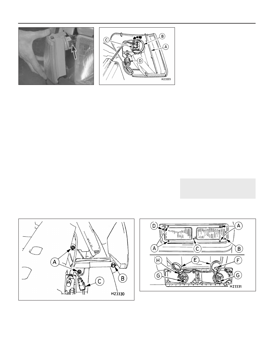
7.24  Auxiliary light assembly (XR2i models) - left-hand unit shown

A Light assembly retaining

screws

B Fog light vertical adjustment

screw

C Driving light vertical adjustment

screw

D Driving light horizontal

adjustment screw

E Bulb protective caps
F Fog light bulb connector
G Bulb earth leads
H Driving light bulb connector

7.21  Auxiliary light fixture (S models)

A Bracket retaining nuts

C Auxiliary light multi-plug

B Auxiliary light retaining nut

7.14  Press the retaining lugs on the rear
light cluster bulbholder together (broken

arrows) to release the bulbholder

7.7b  . . . then pull the light unit out to
enable the multi-plug (arrowed) to be

disconnected

1595Ford Fiesta Remake

work should therefore be carried out by a
Ford dealer or service station with the
necessary facilities.
Temporary adjustment can be made when
the headlight has been removed and refitted,
or to compensate for normal adjustment
whenever a heavy load is being carried. Turn
the adjustment screws at the rear of the
headlight unit to make the adjustment (see
illustration)
.
Before making any adjustments to the
headlight settings, it is important that the tyre
pressures are correct, and that the vehicle is
standing on level ground. Bounce the front of
the vehicle a few times to settle the
suspension. Ideally, somebody of normal size
should sit in the driver’s seat during the
adjustment, and the vehicle should have a full
tank of fuel.
S model auxiliary lights are adjusted by
slackening the light retaining nuts and
swivelling the light assemblies (see
illustration 7.21)
. Tighten the nuts upon
completion.
XR2i model auxiliary lights are individually
adjustable within their housings, provision
being made for both vertical and horizontal
adjustment of the driving lights, and vertical

adjustment only of the foglights. Adjustment is
made via Torx-head captive screws on the
front of the housings (see illustration 7.24).
Whenever temporary adjustments are
made, the settings must be reset as soon as
possible once the vehicle is in normal use.

9

Instrument panel 
removal and refitting

2

Removal

Disconnect the battery negative (earth) lead
(refer to Chapter 5A, Section 1).
Disconnect the speedometer cable at the
transmission casing (see Section 11).
Remove the two screws securing the
instrument panel bezel from its underside.
Remove the bezel.
Remove the four screws securing the
instrument panel to its location, then carefully
pull it out to allow access to the speedometer
cable and multi-plug connections. Disconnect
the speedometer cable and multi-plug, then
remove the instrument panel from the vehicle
(see illustrations).

Refitting

Refitting is a reversal of removal. On
completion check the function of all electrical
components.

10 Instrument panel

components 
removal and refitting

1

Removal

Remove the instrument panel as described
in Section 9.

Panel illumination and warning light
bulbs

All bulbholders are a bayonet fit, requiring a
“twist and withdraw” removal technique (see
illustration)
. Bulbs cannot be removed from
their holders -they are renewed complete.

Printed circuit

Insert a thin flat-bladed screwdriver into the
multi-plug retainer and carefully unclip it,
having noted its orientation (see illustration).
Remove all panel illumination and warning
light bulbholders.
Using a suitable tool (a trim clip removal
tool is ideal), carefully prise the printed circuit
off its instrument terminals, and release it from
its retainers before removing.

Speedometer

Remove the two bulbholders on the top of
the panel assembly, and release their strip of
printed circuit from its retainers, so that the
instrument panel halves may be separated.
Separate the panel halves by releasing the

Body electrical systems  12•11

9.4b  Disconnect the speedometer cable

from the rear of the instrument cluster . . .

9.4a  Instrument cluster securing screws

(arrowed)

8.2  Exploded view of the headlight unit

A Sidelight bulb holder
B Sidelight bulb
C Headlight bulb retainer
D Headlight bulb
E Bulb protective cap
F Horizontal adjustment screw
G Vertical adjustment screw

10.3  Unclipping the multi-plug retainer

from the rear of the instrument cluster

10.2  Removing a bulbholder from the rear

of the instrument cluster (bayonet type

fitting)

9.4c  . . . then disconnect the multi-plug

12

1595Ford Fiesta Remake

retaining tags, taking care to avoid damaging
or losing the warning light graphic strips (see
illustration)
.
Remove its two Torx-head retaining
screws, then detach and withdraw the
speedometer from the front of the assembly.

Tachometer

Carry out the procedure given in
paragraphs 6 and 7.
10 Carefully prise the printed circuit from the
tachometer terminals, using a similar method
to that described in paragraph 5, releasing it
from its retainers as necessary.
11 Remove its two Torx-head retaining
screws, then unclip and withdraw the
tachometer from the front of the assembly.

Fuel and temperature gauge
assembly

12 Removal and refitting procedures are
similar in method to those for the tachometer,
but only one Torx-head screw retains the
assembly.

Refitting

13 Refitting is a reversal of removal.

11 Speedometer cable 

removal and refitting

2

Removal

Remove the instrument panel as described
in Section 9.
Unscrew the speedometer cable from the
pinion/speed sensor on the transmission (see
illustration)
.
Release the cable-ties and retaining clips in
the engine compartment, and withdraw the
cable grommet from the bulkhead.

Note the cable routing for use when
refitting. Pull the speedometer cable through
into the engine compartment, and remove it
from the car.

Refitting

Refitting is the reversal of removal. Ensure
that the cable is routed as noted before
removal, secured with the relevant clips and
cable-ties, and that the grommet is properly
located in the bulkhead.

12 Cigarette lighter 

removal and refitting

1

Removal

Disconnect the battery negative (earth) lead
(refer to Chapter 5A, Section 1).
Remove the cigarette lighter element
(heated section).
Carefully prise the element barrel out from
the illuminated surround, disconnecting its
multi-plug as it is withdrawn.
Hinge the illuminated surround out
carefully, removing its bulb feed connector as
it is withdrawn.

Refitting

Refitting is a reversal of the removal
procedure.

13 Clock 

removal and refitting

1

Removal

Disconnect the battery negative (earth) lead
(refer to Chapter 5A, Section 1).
Using a thin flat-bladed screwdriver,
carefully prise the clock out of the facia (see
illustration)
. Use a piece of card or similar to
prevent damage to the facia. Withdraw the
clock so that its multi-plug may be
disconnected, then remove it from the vehicle.

Refitting

Refitting is a reversal of removal. Reset the
clock on completion.

14 Horn 

removal and refitting

1

Removal

The horn is mounted forward on the left-
hand side of the engine compartment, near
the battery.
Disconnect the battery negative (earth) lead
(refer to Chapter 5A, Section 1).
Remove the wiring loom connection from
the horn(s).
Both single and dual horns are mounted to
a bracket which is secured to the bodywork
by a single bolt. Remove the bolt and
withdraw the horn(s) and bracket from the
vehicle. The horn(s) may be separated from
the bracket, as required, by removing the
retaining nut(s).

Refitting

Refitting is a reversal of removal.

15 Wiper arms 

removal and refitting

1

Removal

With the wiper(s) “parked” (ie in the normal
at-rest position), mark the positions of the
blade(s) on the screen, using a wax crayon or
strips of masking tape.
Lift up the plastic cap from the bottom of
the wiper arm, and loosen the nut one or two
turns.
Lift the wiper arm, and release it from the
taper on the spindle by moving it from side to
side.
Completely remove the nut and washer,
then withdraw the wiper arm from the 
spindle.

Refitting

Refitting is a reversal of the removal
procedure. Make sure that the arm is fitted in
the previously-noted position.

12•12 Body electrical systems 

13.2  Carefully prise the clock out of the

facia

11.2  Detaching the speedometer cable at

the transmission casing

10.7  Rear view of instrument cluster

A Retaining tags
B Multi-plug retainer
C Speedometer cable connection
D Speedometer gauge retaining screws
E Tachometer terminals (obscured by

protective pad)

F Tachometer gauge retaining screws
G Fuel and temperature gauge assembly

terminals

H Fuel and temperature gauge assembly

retaining screw

1595Ford Fiesta Remake

16 Windscreen wiper motor and

linkage - removal and refitting

2

Removal

Wiper motor

Operate the wiper motor, then switch it off
so that it returns to its rest position.
Disconnect the battery negative (earth) lead
(refer to Chapter 5A, Section 1).
Dependent on model, disconnect and
remove the air cleaner components as
necessary to allow access to remove the
bulkhead panel.
Remove the cooling system expansion tank
as described in Chapter 3.
Release the wiring loom, any connectors,
cable-ties and hoses from the right-hand half
of the bulkhead panel, then remove its rubber
seal.
The right-hand half of the bulkhead panel is
secured by screws and a single nut. The nut is
located behind the panel at the bonnet hinge
end. Release the right-hand half of the panel
and, having ensured that it is free to move,
remove it (see illustrations).
Unscrew the nut from the driving shaft, and
pull the crank off the driving shaft taper (see
illustration)
.
Undo the three wiper motor retaining bolts

and withdraw the motor assembly (see
illustrations)
. Remove the motor cover, then
disconnect the multi-plug and remove the
motor from the vehicle.

Linkage

Pull the rubber seal off the bulkhead panel.
10 Bring the windscreen wiper linkage to an
accessible position, using the ignition switch
as a means of stopping the wiper motor
returning to the parked position.
11 Disconnect the battery negative (earth)
lead (refer to Chapter 5A, Section 1).
12 Prise the linkages off their ball pivots as
required, using a suitably-sized open-ended
spanner. The crank has a dual (vertically
stacked) ball pivot with a bellows separating
the two linkages (see illustrations).
13 If the running faces of the ball pivots are
damaged, the pivot shaft(s) or crank must be
renewed.

Refitting

Wiper motor

14 Refitting is a reversal of the removal
procedure, tightening all nuts and bolts to the
specified torque. Refit the expansion tank as
described in Chapter 3.

Linkage

15 Prior to refitting, grease the ball pivot
sockets on the linkages, then locate them on
their appropriate ball pivots and press into

position using a suitably-sized socket. The
bellows between the two linkages on the
crank must also be greased using the
specified lubricant. Refit the bulkhead panel
rubber seal on completion.

17 Windscreen wiper pivot

shaft - removal and refitting

2

Removal

Remove the windscreen wiper arms as
described in Section 15.

Body electrical systems  12•13

16.7  Unscrew the nut from the wiper

motor driving shaft

16.6b  . . . then disengage the right-hand

half of the panel from under its single

retaining nut (left-hand shown)

16.6a  Remove all retaining screws from

the right-hand half of the bulkhead panel

(upper centre screw shown) . . .

16.12b  Windscreen wiper motor bracket

with linkage and motor. Inset shows

bellows arrangement (A)

16.8a  With the crank removed from the

driving shaft taper, undo the three wiper

motor retaining bolts (arrowed)

16.12a  Windscreen wiper linkage

A  Removal       B  Refitting

16.8b  . . . and withdraw the wiper motor

assembly

12

1595Ford Fiesta Remake


Content   ..  56  57  58  59   ..