Dongfeng DFA1101GZ5AD6J-907. Manual - part 66


  Index      Dongfeng     Dongfeng DFA1101GZ5AD6J-907 (Truck) - service manual 2006 year


Search            


Content   ..  64  65  66 


Dongfeng DFA1101GZ5AD6J-907. Manual - part 66


Electric and Instrument

EL-20

Structure

The speedometer is used to indicate the vehicle driving speed and

the accumulated driving distance. It comprises a speed and a mileage
unit which records vehicle driving mileage. These two units are inte-
grated into one body and driven by the flexible shaft which is connected
with transmission output shaft.

The mileage unit records the driven mileage of the vehicle in order

to do necessary maintenance on mileage. The counter is divided into an
accumulated counter and a day counter. The speed unit indicates the
transient speed of the vehicle. It is convenient to control the vehicle
speed so as to obtain safety, economy and high efficiency.

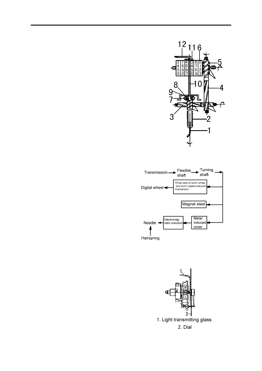
1.Flexible shaft    2.Drive shaft     3.Worm and lateral shaft 

4.Worm and vertical shaft    5.Worm wheel    6.Digital wheel

7.Magnetic ring     8.Temperature compensated ring   

9.Inductive aluminum cover    10.Needle shaft   

11.Hairspring     12.Needle

Working principle

Drive of speedometer

The flexible shaft (driven by transmission main

shaft) mounted on the back of the transmission is driven
by pulling the square connector into the square hole at
the outside of the speedometer turning shaft which drives
the digital wheel through three sets of worm wheel and
worm.

Indication of odometer

When the flexible shaft drives the speedometer turn-

ing shaft to rotate, the magnetic steel on the drive shaft
rotates simultaneously, causing the eddy current within
the inductive cover, which also produce magnetic field.
Both fields interact on each other to produce deflecting
torque. The higher the vehicle speed is, the larger the
deflecting torque is, which can be indicated by the needle
deflection. When the needle deflecting torque of the hair-
spring, the needle will stay at the appropriate speed
value. The needle deflecting angle is proportional to the
speed of the speedometer turning shaft, that is, the vehi-
cle speed, causing the needle to indicate various speed.

Electric and Instrument

EL-21

Trouble analysis

Trouble

Cause

Method

Both the speed 
division and the 
distance count-
ing division of 
the speedometer 
do not work

Flexible shaft core broken

Replace

Odometer rotating shaft seized

Replace the odometer

Square connector nut slackened

Tighten again

Only the speed 
division of the 
speedometer does 
not work

Needle deformed and seized with dial or glass

Correct

Drive worm wheel and worm, and inductive plate 
seized, broken, or dirtied

Replace or clean

The needle and 
the accumulated 
machine do not 
run simulta-
neously

Drive gear or driven gear of the speedometer dam-
aged

Replace meter

Meter failed

Replace meter

The deflection 
indication of the 
needle is too 
high.

Speedometer flexible shaft deformed or radius 
area bent

Correct the flexible shaft

Input shaft or gear worn

Replace meter

The speedometer 
indication is on 
the low side

Transmission output shaft slipped

Tighten the flange fork under the rec-

ommended torque

The magnetic effect of the magnetic steel reduced

Replace

Needle indica-
tion error

Hairspring deformed or deviate from the original 
position

Move the hairspring to one side to 

adjust the indication of the needle

Magnetic body cracked

Replace meter

Dimension of tyre is wrong

Replace and use the recommended tyre

Speed gear worn or damaged

Replace meter

The needle 
deflection 
exceeds the dial

Grease on the magnet

Clean out the grease

The speed needle 
of the speedome-
ter works 
unsteadily

Hairspring broken

Replace meter

At the constance velocity of the vehicle when the 
speed needle's indication unsteadily reaches to 
3km/h, it is in trouble. Check the curvature of the 
flexible shaft to see if it is too small.

Adjust

Flexible shaft core seized

Clean and lubricate

Speedometer nee-
dle oscillates 
severely

The axial clearance of the flexible shaft is too big 
causes the flexible shaft and speedometer's rotat-
ing shaft sometimes engaged, sometimes sepa-
rated.

Replace shaft core

Electric and Instrument

EL-22

Tachometer

Dial description

The needle of the electronic tachometer indicates the engine speed in revolu-

tions per minute. The red zone indicates the range of the critical engine speed.
Strictly be sure to always keep the indicator below this critical zone. The green
zone indicates the most economical engine operation. Driving within this green
zone will save fuel and extend the engine life.

Technical specification

Constructional description

The electronic tachometer construction including:

The indication division: comprise of needle, dial

and so on.

The signal processing division: comprise of printed-

circuit plate and electronic parts.

The measuring mechanism: comprise of magnetic

steel, pole plate, pole ring, and needle shaft coil assem-
bly, bracket assembly, upper and lower bearing and so
on.

Auxiliary part: Base, housing, screws and electrical

connectors.

The needle seized 
or failed that can 
not return to zero

Grease on the magnet

Clean out the grease

Hairspring deformed

Replace meter

Wrong assembling of the needle (needle slack-
ened)

Tighten

There are impurities absorbed on the magnet of the 
indication board.

Clean

The day distance 
counter does not 
work or can not 
return to zero

Odometer drive pinion damaged

Repair or replace

Return zero button damaged

Repair or replace

Speedometer 
noise

Speedometer bearing worn and damaged

Replace meter

Speedometer gear lacks of lubricating and causing 
worn

Fill with grease

Speedometer flexible shaft lacks of lubricating and 
causing worn

Fill with grease

Type Moving 

coil

Range(r/min)

0~5000

Deflecting angle(º)

245

Min. graduation (r/min)

100

Accuracy level

1.5

Connector

DJ7043-6.3-20 type, 4-cable combined socket

Trouble

Cause

Method

Electric and Instrument

EL-23

Instrument assembly and disassembly

Before disassembling the instrument, pull out needle 1, and then

loosen two screws 2.

When disassembling the printed-circuit board; pull it out directly

after welding off two wires 9(the printed board and blade connector are
directly connected together through a spring blade socket on the board).

Generally, do not disassemble the unit core. If it has to be disassem-

bled, weld off both the upper and the lower hairsprings, and the conduc-
tive blade at first so as not to damage the hairsprings In addition, do not
break the coil output wire.

1.Needle   2.Screw    3.Dial    4.Light guiding glass    

5.Printed circuit-board     6.Connection wire    7.Bracket

8.Blade connector    9.Base

Trouble analysis

Trouble

Case

Repair

The instrument doesn't 
work

Circuit broke

Sensor damaged
Instrument burnt out 

Check wire connection and connector with 
socket's contact
Replace sensor
Replace instrument

Needle shakes abnor-
mally

Wire connection is not good
Integrated body damaged

Check wire connection
Replace integrated body

Needle clicked

There's foreign objects in the core 

Remove foreign objects

Needle doesn't return 
to zero

Needle slacked
Core is clicked by foreign objects

Press the needle firmly and turn to zero
Remove foreign objects


Content   ..  64  65  66