Dodge Sprinter. Manual - part 516


  Index      Dodge     Dodge Sprinter / Mercedes-Benz - service repair manual 2006 year


Search            


Content   ..  514  515  516  517   ..


Dodge Sprinter. Manual - part 516


Symptom:

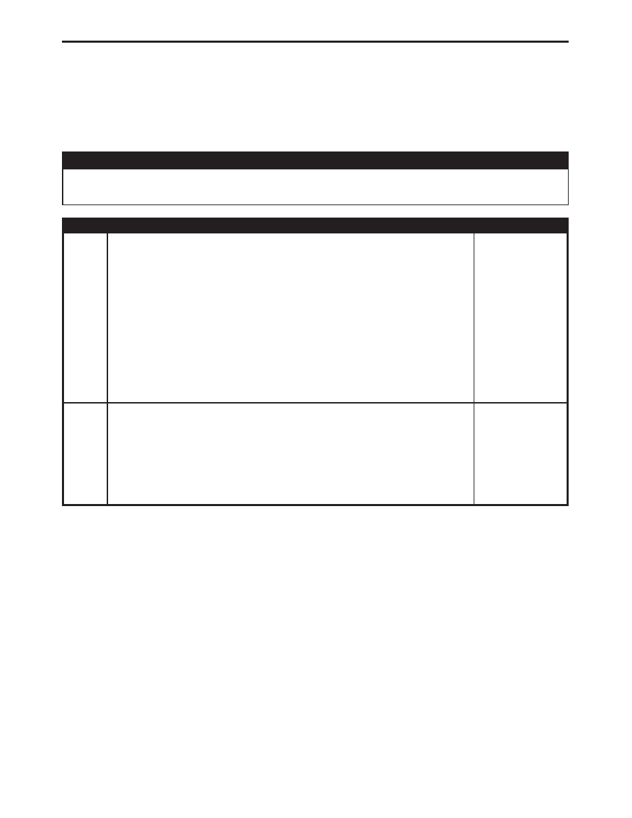
*CHECKING THE FUEL PRESSURE SOLENOID CIRCUITS

POSSIBLE CAUSES

FUEL PRESSURE SOLENOID RESISTANCE

OPEN CIRCUITS

TEST

ACTION

APPLICABILITY

1

Turn the ignition off.
Disconnect the Fuel Pressure Solenoid harness connector.
Disconnect the ECM harness connectors.
Visually inspect the related wiring harness. Look for any chafed, pierced, pinched, or
partially broken wires. Repair as necessary.
Visually inspect the related wiring harness connectors. Look for broken, bent, pushed
out, or corroded terminals. Repair as necessary.
Measure the resistance of both Fuel Pressure Solenoid circuits between the ECM
harness connector and the Fuel Pressure Solenoid harness connector.
Is the resistance below 10.0 ohms for both measurements?

All

Yes

→ Go To 2

No

→ Repair open circuit(s) as necessary.

Perform ROAD TEST VERIFICATION - VER-2.

2

Turn the ignition off.
Disconnect the Fuel Pressure Solenoid harness connector.
Measure the resistance of the Fuel Pressure Solenoid.
Is the resistance between 3.5 and 5.5 ohms?

All

Yes

→ Test Complete.

No

→ Replace the Fuel Pressure Solenoid.

Perform ROAD TEST VERIFICATION - VER-2.

233

DRIVEABILITY - DIESEL

Symptom:

*CHECKING THE FUEL QUANTITY SOLENOID CIRCUITS

POSSIBLE CAUSES

OPEN CIRCUITS

TEST

ACTION

APPLICABILITY

1

Turn the ignition off.
Disconnect the Fuel Quantity Solenoid harness connector.
Disconnect the ECM harness connectors.
Visually inspect the related wiring harness. Look for any chafed, pierced, pinched, or
partially broken wires. Repair as necessary.
Visually inspect the related wiring harness connectors. Look for broken, bent, pushed
out, or corroded terminals. Repair as necessary.
Measure the resistance of both Fuel Quantity Solenoid circuits between the ECM
harness connector and the Fuel Quantity Solenoid harness connector.
Is the resistance below 10.0 ohms for both measurements?

All

Yes

→ Test Complete.

No

→ Repair open circuit(s) as necessary.

Perform ROAD TEST VERIFICATION - VER-2.

234

DRIVEABILITY - DIESEL

Symptom:

*CHECKING THE POWER AND GROUNDS

POSSIBLE CAUSES

CHECKING THE ENGINE CONTROL RELAY SYSTEM

EC RELAY OUTPUT CIRCUIT

ECM GROUND CIRCUIT(S) OPEN

ECM OUTPUT SHORTED - FUSE 16

ENGINE CONTROL MODULE

ENGINE CONTROL RELAY

ENGINE CONTROL RELAY B+ SUPPLY

ENGINE CONTROL RELAY CONTROL CIRCUIT OPEN

ENGINE CONTROL RELAY CONTROL CIRCUIT SHORT TO VOLTAGE

ENGINE CONTROL RELAY OUTPUT CIRCUIT(S) OPEN

ENGINE CONTROL RELAY OUTPUT CKT SHORTED TO GROUND FUSE #16

ENGINE CONTROL RELAY OUTPUT CKT SHORTED TO GROUND FUSE #17

IGNITION SWITCH START OUTPUT CIRCUIT OPEN

IGNITION SWITCH START/RUN OUTPUT CIRCUIT OPEN

SHORTED COMPONENT

TEST

ACTION

APPLICABILITY

1

Turn the ignition off.
Disconnect the ECM harness connectors.
Using a 12-volt test light connected to 12-volts, check each of the ECM ground
circuits in ECM harness connector C2 cavities 2, 4 and 6.
Did the test light illuminate brightly for each cavity?

All

Yes

→ Go To 2

No

→ Repair the ECM Ground circuit(s) for an open.

Perform ROAD TEST VERIFICATION - VER-2.

2

Turn the ignition off.
Disconnect the ECM harness connectors.
Turn the ignition switch to the Start position.
Using a 12-volt test light connected to ground, check the Fused Ignition Switch Start
Output circuit in ECM C2 harness connector cavity 36.
Does the test light illuminate brightly?

All

Yes

→ Go To 3

No

→ Repair the Ignition Switch Start Output circuit for an open.

Perform ROAD TEST VERIFICATION - VER-2.

235

DRIVEABILITY - DIESEL

TEST

ACTION

APPLICABILITY

3

Turn the ignition off.
Disconnect the ECM harness connectors.
Turn the ignition switch to the Start position.
Using a 12-volt test light connected to ground, check the Fused Ignition Switch
Start/Run Output circuit in ECM C2 harness connector cavity 19.
Repeat the previous step with the ignition switch in the Run position.
Does the test light illuminate brightly in the Start and Run positions?

All

Yes

→ Go To 4

No

→ Repair the Ignition Switch Start/Run Output circuit for an open.

Perform ROAD TEST VERIFICATION - VER-2.

4

Turn the ignition off.
Remove the Engine Control Relay from Fuse Block No. 1.
Using a 12-volt test light connected to 12-volts, check the Engine Control Relay
Control circuit in the Engine Control Relay connector in Fuse Block No. 1.
Turn the ignition on.
Does the test light illuminate?

All

Yes

→ Go To 5

No

→ Go To 14

5

Turn the ignition off.
Remove and inspect Fuse #17 from Fuse Block No.1.
Is the fuse open?

All

Yes

→ Go To 6

No

→ Go To 8

6

Turn the ignition off.
Disconnect the ECM harness connectors.
Disconnect the EGR Valve harness connector.
Disconnect the Boost Pressure Solenoid harness connector.
Remove the Starter Relay.
Remove the Lift Pump Relay.
Install a good fuse in place of Fuse #17 in Fuse Block No.1
Connect a jumper wire between ground and the Engine Control Relay Control circuit
in ECM C2 harness connector cavity 44.
Turn the ignition on.
Remove and inspect Fuse #17 in Fuse Block No. 1.
Is the fuse open?

All

Yes

→ Repair the Engine Control relay Output circuit for a short to

ground.
Perform ROAD TEST VERIFICATION - VER-2.

No

→ Go To 7

7

NOTE: A short circuit exists in one of the following: Lift Pump Relay, Starter
Relay, EGR Valve, Boost Pressure Servo Motor or ECM.
View repair.

All

Yes

→ Using the Service Information wiring check the listed components

for short circuits. Replace the shorted component as necessary.
Perform ROAD TEST VERIFICATION - VER-2.

236

DRIVEABILITY - DIESEL

*CHECKING THE POWER AND GROUNDS —

Continued


Content   ..  514  515  516  517   ..