Dodge Sprinter. Manual - part 300


  Index      Dodge     Dodge Sprinter / Mercedes-Benz - service repair manual 2006 year


Search            


Content   ..  298  299  300  301   ..


Dodge Sprinter. Manual - part 300


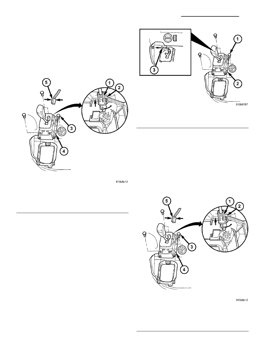
(4) Disconnect the park lock cable coupling (1)

(Fig. 224) from the shift lever assembly (SLA). Press
locking tab (2) together and push coupling (1) against
the spring force into the SLA, twist through 90°
(right or left) and pull off.

(5) Disconnect connector plug (5) from SLA. When

disconnecting plug, press together at points shown
(arrows).

(6) Pry ball socket (4) of transmission shift cable

off ball knob at the SLA. Use a suitable slotted
screwdriver.

(7) Unscrew bolts (1) (Fig. 225).
(8) Move selector lever to position “P”.
(9) Remove the SLA (2) from the vehicle.

INSTALLATION

(1) Position the shift lever assembly (SLA) onto

the vehicle.

(2) Install the bolts to hold the SLA to the vehicle.

Tighten the bolts to 6 N·m (53 in.lbs.).

(3) Connect the park lock cable coupling (1) (Fig.

226) to the SLA. Press locking tab (2) together and
push coupling (1) against the spring force into the
SLA, twist through 90° (right or left) until locked.

(4) Connect the connector plug (5) to the SLA.

Fig. 224 Disengage Park Lock Cable From SLA

1 - PARK LOCK CABLE COUPLING
2 - LOCK TAB
3 - BOLT
4 - SHIFT LEVER ASSEMBLY (SLA)
5 - CONNECTOR

Fig. 225 Remove SLA

1 - BOLT
2 - SLA
3 - SHIFT CABLE

Fig. 226 Engage Park Lock Cable to SLA

1 - PARK LOCK CABLE COUPLING
2 - LOCK TAB
3 - BOLT
4 - SHIFT LEVER ASSEMBLY (SLA)
5 - CONNECTOR

21 - 170

AUTOMATIC TRANSMISSION NAG1 - SERVICE INFORMATION

VA

(5) Turn on ignition and apply brakes. Move selec-

tor lever back to position “D”.

(6) Install the transmission shift cable onto the

ball knob at the SLA.

(7) Install the bottom (2) (Fig. 227) of the center

section of instrument panel.

(8) Install the top (3) (Fig. 228) of the center sec-

tion of instrument panel.

(9) Verify repair.

SOLENOID

DESCRIPTION

The typical electrical solenoid used in automotive

applications is a linear actuator. It is a device that
produces motion in a straight line. This straight line
motion can be either forward or backward in direc-
tion, and short or long distance.

A solenoid is an electromechanical device that uses

a magnetic force to perform work. It consists of a coil
of wire, wrapped around a magnetic core made from
steel or iron, and a spring loaded, movable plunger,
which performs the work, or straight line motion.

The solenoids used in transmission applications

are attached to valves which can be classified as nor-
mally open 
or normally closed. The normally
open 
solenoid valve is defined as a valve which
allows hydraulic flow when no current or voltage is
applied to the solenoid. The normally closed sole-
noid valve is defined as a valve which does not allow
hydraulic flow when no current or voltage is applied
to the solenoid. These valves perform hydraulic con-
trol functions for the transmission and must there-
fore be durable and tolerant of dirt particles. For
these reasons, the valves have hardened steel pop-
pets and ball valves. The solenoids operate the valves

Fig. 227 Install Bottom Section Of Center

Instrument Panel

1 - SCREW
2 - BOTTOM CENTER PART OF INSTRUMENT PANEL

Fig. 228 Install Top Section Of Center Instrument

Panel

1 - SHIFT LEVER ASSEMBLY FRAME TRIM
2 - STORAGE COMPARTMENT
3 - TOP CENTER PART OF INSTRUMENT PANEL
4 - SCREW
5 - PLUG CONNECTIONS
6 - ASHTRAY

VA

AUTOMATIC TRANSMISSION NAG1 - SERVICE INFORMATION

21 - 171

directly, which means that the solenoids must have
very high outputs to close the valves against the siz-
able flow areas and line pressures found in current
transmissions. Fast response time is also necessary
to ensure accurate control of the transmission.

The strength of the magnetic field is the primary

force that determines the speed of operation in a par-
ticular solenoid design. A stronger magnetic field will
cause the plunger to move at a greater speed than a
weaker one. There are basically two ways to increase
the force of the magnetic field:

1. Increase the amount of current applied to the

coil or

2. Increase the number of turns of wire in the coil.
The most common practice is to increase the num-

ber of turns by using thin wire that can completely
fill the available space within the solenoid housing.
The strength of the spring and the length of the
plunger also contribute to the response speed possi-
ble by a particular solenoid design.

A solenoid can also be described by the method by

which it is controlled. Some of the possibilities
include variable force, pulse-width modulated, con-
stant ON, or duty cycle. The variable force and pulse-
width modulated versions utilize similar methods to
control the current flow through the solenoid to posi-
tion the solenoid plunger at a desired position some-
where between full ON and full OFF. The constant
ON and duty cycled versions control the voltage
across the solenoid to allow either full flow or no flow
through the solenoid’s valve.

UPSHIFT / DOWNSHIFT SOLENOID VALVES

The solenoid valves (1) for upshifts and downshifts

(Fig. 229) are located in the shell of the electric con-
trol unit and pressed against the shift plate with a
spring.

The solenoid valves (1) initiate the upshift and

downshift procedures in the shift plate.

The solenoid valves (1) are sealed off from the

valve housing of the shift plate (5) by two O-rings (4,
6). The contact springs (8) at the solenoid valve
engage in a slot in the conductor tracks (7). The force
of the contact spring (8) ensures safe contacts.

Fig. 229 Upshift/Downshift Solenoid Valves

1 - UPSHIFT/DOWNSHIFT SOLENOID VALVE
2 - CONTACT SPRING
3 - CONDUCTOR TRACK
4 - O-RING
5 - VALVE HOUSING OF SHIFT PLATE
6 - O-RING
7 - CONDUCTOR TRACK
8 - CONTACT SPRING

21 - 172

AUTOMATIC TRANSMISSION NAG1 - SERVICE INFORMATION

VA

MODULATING PRESSURE CONTROL SOLENOID
VALVE

The modulating pressure control solenoid valve (1)

(Fig. 230) is located in the shell of the electric valve
control unit and pressed against the shift plate by a
spring.

Its purpose is control the modulating pressure

depending on the continuously changing operating
conditions, such as load and gear change.

The modulating pressure regulating solenoid valve

(1) has an interference fit and is sealed off to the
valve body of the shift plate (4) by a seal (arrow). The
contact springs (2) at the solenoid valve engage in a
slot in the conductor tracks (3). The force of the con-
tact springs (2) ensures secure contacts.

TORQUE CONVERTER LOCKUP CLUTCH PWM
SOLENOID VALVE

The torque converter lockup clutch PWM solenoid

valve (1) (Fig. 231) is located in the shell of the elec-
tric valve control unit and pressed against the shift
plate by a spring.

The PWM solenoid valve (1) for the torque con-

verter lockup controls the pressure for the torque
converter lockup clutch.

The torque converter lockup PWM solenoid valve

(1) is sealed off to the valve body of the shift plate (4)
by an O-ring (5) and a seal (arrow). The contact
springs (2) at the solenoid valve engage in a slot in
the conductor tracks (3). The force of the contact
springs (2) ensures secure contacts.

Fig. 230 Modulating Pressure Control Solenoid

Valve

1 - MODULATING PRESSURE CONTROL SOLENOID VALVE
2 - CONTACT SPRING
3 - CONDUCTOR TRACK
4 - VALVE HOUSING SHIFT PLATE
5 - CONDUCTOR TRACK
6 - CONTACT SPRING

Fig. 231 Torque Converter Lockup Clutch PWM

Solenoid Valve

1 - TORQUE CONVERTER LOCKUP CLUTCH PWM SOLENOID
VALVE
2 - CONTACT SPRING
3 - CONDUCTOR TRACK
4 - VALVE HOUSING OF SHIFT PLATE
5 - O-RING
6 - CONDUCTOR TRACK
7 - CONTACT SPRING

VA

AUTOMATIC TRANSMISSION NAG1 - SERVICE INFORMATION

21 - 173


Content   ..  298  299  300  301   ..