Dodge Sprinter. Manual - part 297


  Index      Dodge     Dodge Sprinter / Mercedes-Benz - service repair manual 2006 year


Search            


Content   ..  295  296  297  298   ..


Dodge Sprinter. Manual - part 297


INSTALLATION

CAUTION: Verify that the geartrain end-play shim is
properly installed over the output shaft and against
the park gear.

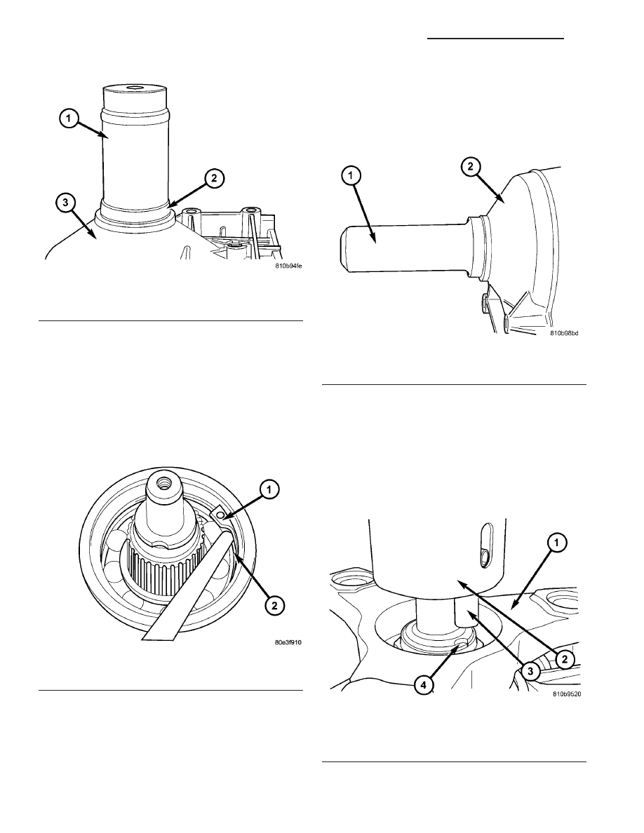
(1) Install output shaft bearing in the rear trans-

mission housing. Using Bearing Installer 9287 (1)
(Fig. 195), install the output shaft bearing (2) into
the transmission housing. The closed side of the
plastic cage must point towards the parking
lock gear.

(2) Install the retaining ring (1) (Fig. 196). Ensure

that the retaining ring is seated correctly in the
groove.

(3) Check that there is no play between the bear-

ing and the retaining ring using feeler gauge.

(4) There must be no play between the retaining

ring and the bearing. If the ring cannot be installed,

a thinner ring must be used. If there is play between
the ring and the bearing, a thicker ring must be
installed. Retaining rings are available in thick-
nesses of 2.0 mm (0.079 in.), 2.1 mm (0.083 in.), and
2.2 mm (0.087 in.).

(5) Install the output shaft washer onto the output

shaft.

(6) Install a new transmission rear seal into the

transmission case with Seal Installer 8902A (1) (Fig.
197).

(7) Verify that the transmission is in PARK in

order to prepare for the installation of the output
shaft nut.

(8) Install the propeller shaft flange onto the out-

put shaft and install an new flange nut. Tighten the
flange nut to 200 N·m (147.5 ft.lbs.).

Fig. 195 Install Output Shaft Bearing

1 - BEARING INSTALLER 9287
2 - BEARING
3 - TRANSMISSION CASE

Fig. 196 Install Rear Output Shaft Retaining Ring

1 - RETAINING RING
2 - OUTPUT SHAFT BEARING

Fig. 197 Install Output Shaft Seal

1 - SEAL INSTALLER 8902A
2 - TRANSMISSION CASE

Fig. 198 Align Staking Tool 9078

1 - PROPELLER SHAFT FLANGE
2 - STAKING TOOL 9078
3 - ALIGNMENT PIN
4 - OUTPUT SHAFT NOTCH

21 - 158

AUTOMATIC TRANSMISSION NAG1 - SERVICE INFORMATION

VA

(9) Stake the output shaft nut to the output shaft

as follows.Place the Staking Tool 9078 (2) and Driver
Handle C-4171 onto the output shaft.

(10) Rotate the Staking Tool 9078 (2) until the

alignment pin (3) engages the output shaft notch (4)
(Fig. 198).

(11) Press downward on the staking tool (1) until

the staking pin (3) contacts the output shaft nut
flange (2) (Fig. 199).

(12) Strike the Driver handle C-4171 with a suit-

able hammer until the output shaft nut is securely
staked to the output shaft.

(13) Install the propeller shaft (Refer to 3 - DIF-

FERENTIAL & DRIVELINE/PROPELLER SHAFT/
PROPELLER SHAFT - INSTALLATION).

OUTPUT SHAFT SEAL

REMOVAL

(1) Remove the propeller shaft (Refer to 3 - DIF-

FERENTIAL & DRIVELINE/PROPELLER SHAFT/
PROPELLER SHAFT - REMOVAL). Move propeller
shaft to the right and tie up.

(2) Verify that the transmission is in PARK in

order to prepare for the removal of the output shaft
nut.

(3) Remove the nut holding the propeller shaft

flange to the output shaft and remove the flange.

(4) Remove the output shaft seal with suitable

screw and slide hammer.

INSTALLATION

(1) Position the new output shaft seal over the out-

put shaft and against the transmission case.

(2) Use Seal Installer 8902A (1) (Fig. 200) to

install the seal.

(3) Verify that the transmission is in PARK in

order to prepare for the installation of the output
shaft nut.

(4) Install the propeller shaft flange onto the out-

put shaft and install an new flange nut. Tighten the
flange nut to 200 N·m (147.5 ft.lbs.).

(5) Stake the output shaft nut to the output shaft

as follows.Place the Staking Tool 9078 (2) and Driver
Handle C-4171 onto the output shaft.

(6) Rotate the Staking Tool 9078 (2) until the

alignment pin (3) engages the output shaft notch (4)
(Fig. 201).

Fig. 199 Stake Output Shaft Nut

1 - STAKING TOOL 9078
2 - PROPELLER FLANGE
3 - STAKING PIN

Fig. 200 Install the Output Shaft Seal

1 - SEAL INSTALLER 8902A
2 - TRANSMISSION CASE

Fig. 201 Align Staking Tool 9078

1 - PROPELLER SHAFT FLANGE
2 - STAKING TOOL 9078
3 - ALIGNMENT PIN
4 - OUTPUT SHAFT NOTCH

VA

AUTOMATIC TRANSMISSION NAG1 - SERVICE INFORMATION

21 - 159

(7) Press downward on the staking tool until the

staking pin (3) contacts the output shaft nut flange
(2) (Fig. 202).

(8) Strike the Driver handle C-4171 with a suit-

able hammer until the output shaft nut is securely
staked to the output shaft.

(9) Install the propeller shaft (Refer to 3 - DIF-

FERENTIAL & DRIVELINE/PROPELLER SHAFT/
PROPELLER SHAFT - INSTALLATION).

PARK LOCK CABLE

REMOVAL

(1) Disconnect battery.
(2) Move selector lever to position “D”.
(3) Remove top section (3) (Fig. 203) of the center

section of instrument panel.

(4) Remove bottom section (2) (Fig. 204) of the cen-

ter section of instrument panel.

Fig. 202 Stake Output Shaft Nut

1 - STAKING TOOL 9078
2 - PROPELLER FLANGE
3 - STAKING PIN

Fig. 203 Remove Top Section Of Center Instrument

Panel

1 - SHIFT LEVER ASSEMBLY FRAME TRIM
2 - STORAGE COMPARTMENT
3 - TOP CENTER PART OF INSTRUMENT PANEL
4 - SCREW
5 - PLUG CONNECTIONS
6 - ASHTRAY

Fig. 204 Remove Bottom Section Of Center

Instrument Panel

1 - SCREW
2 - BOTTOM CENTER PART OF INSTRUMENT PANEL

21 - 160

AUTOMATIC TRANSMISSION NAG1 - SERVICE INFORMATION

VA

(5) Disconnect the park lock cable coupling (1)

(Fig. 205) from the shift lever assembly (SLA). Press
locking tab (2) together and push coupling (1) against
the spring force into the SLA, twist through 90°
(right or left) and pull off.

(6) Remove the lower steering column shroud.
(7) Loosen the park lock cable (2) (Fig. 206) from

the ignition switch.

(8) Remove the park lock cable (2) (Fig. 207) from

the ignition switch.

(9) Remove the park lock cable from the vehicle.

INSTALLATION

(1) Route the park lock cable through the instru-

ment panel between the steering column and the
shift lever assembly (SLA).

(2) Install the park lock cable (2) (Fig. 208) to the

ignition switch.

(3) Tighten the park lock cable (2) (Fig. 209) to the

ignition switch.

(4) Install the lower steering column shroud.

Fig. 205 Disengage Park Lock Cable From SLA

1 - PARK LOCK CABLE COUPLING
2 - LOCK TAB
3 - BOLT
4 - SHIFT LEVER ASSEMBLY (SLA)
5 - CONNECTOR

Fig. 206 Loosen Park Lock Cable From Ignition

Switch

1 - IGNITION SWITCH
2 - PARK LOCK CABLE

Fig. 207 Remove Park Lock Cable From Ignition

Switch

1 - IGNITION SWITCH
2 - PARK LOCK CABLE

Fig. 208 Install Park Lock Cable to Ignition Switch

1 - IGNITION SWITCH
2 - PARK LOCK CABLE

VA

AUTOMATIC TRANSMISSION NAG1 - SERVICE INFORMATION

21 - 161


Content   ..  295  296  297  298   ..