Dodge Sprinter. Manual - part 292


  Index      Dodge     Dodge Sprinter / Mercedes-Benz - service repair manual 2006 year


Search            


Content   ..  290  291  292  293   ..


Dodge Sprinter. Manual - part 292


ASSEMBLY

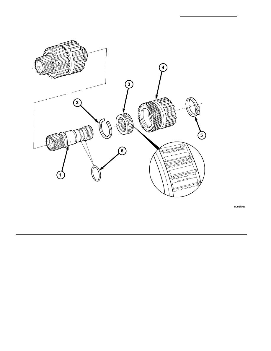
NOTE: The side of the freewheeling clutch F2 (3)
with the markings (directional arrow, part number,
etc.) must be up when the clutch is installed in the
sun gear (4).

(1) Press freewheeling clutch F2 (3) (Fig. 158) into

sun gear (4).

(2) Install snap-ring (2) for freewheeling clutch.
(3) Check O-rings (6) (Fig. 158) on hollow shaft,

replace if necessary.

(4) Install rear sun gear (4) with K3 internally

toothed disc carrier and rear freewheeling clutch (3)
onto the hollow shaft.

(5) Verify proper operation of the freewheeling

clutch F2. When the assembly is held with the F2

clutch snap-ring upward, it should be possible to
rotate the hollow shaft counter-clockwise.

(6) Install retaining ring (5) onto hollow shaft (1).

GEARSHIFT CABLE

DIAGNOSIS AND TESTING

GEARSHIFT CABLE

(1) The floor shifter lever and gate positions

should be in alignment with all transmission PARK,
NEUTRAL, and gear detent positions.

(2) Engine starts must be possible with floor shift

lever in PARK or NEUTRAL gate positions only.

Fig. 158 Freewheeling Clutch F2

1 - HOLLOW SHAFT

4 - K3 INNER DISC CARRIER AND REAR PLANETARY SUN
GEAR

2 - F2 CLUTCH SNAP-RING

5 - RETAINING RING

3 - FREEWHEELING CLUTCH F2

6 - O-RINGS

21 - 138

AUTOMATIC TRANSMISSION NAG1 - SERVICE INFORMATION

VA

Engine starts must not be possible in any other gear
position.

(3) With floor shift lever handle push-button not

depressed and lever in:

(a) PARK position - Apply forward force on cen-

ter of handle and remove pressure. Engine starts
must be possible.

(b) PARK position - Apply rearward force on cen-

ter of handle and remove pressure. Engine starts
must be possible.

(c) NEUTRAL position - Normal position. Engine

starts must be possible.

(d) NEUTRAL position - Engine running and

brakes applied, apply forward force on center of
shift handle. Transmission shall not be able to shift
from NEUTRAL to REVERSE.

REMOVAL

(1) Move selector lever to position “D”.
(2) Remove top (3) (Fig. 159) of the center section

of instrument panel.

(3) Remove bottom (2) (Fig. 160) of the center sec-

tion of instrument panel.

(4) Pry ball socket of transmission shift cable off

ball knob at the shift lever assembly (SLA). Use a
suitable slotted screwdriver.

(5) Raise and support vehicle.
(6) Detach shift cable (1) at transmission.

(a) Unlatch ball socket latch (Fig. 161) of cable.
(b) Unclip shift cable retainer from retainer

bracket. When pulling out cable, press together
hooks of shift cable retainer at the points shown
(arrows).

Fig. 159 Remove Top Section Of Center Instrument

Panel

1 - SHIFT LEVER ASSEMBLY FRAME TRIM
2 - STORAGE COMPARTMENT
3 - TOP CENTER PART OF INSTRUMENT PANEL
4 - SCREW
5 - PLUG CONNECTIONS
6 - ASHTRAY

Fig. 160 Remove Bottom Section Of Center

Instrument Panel

1 - SCREW
2 - BOTTOM CENTER PART OF INSTRUMENT PANEL

Fig. 161 Remove Shift Cable From Transmission

1 - SHIFT CABLE
2 - TRANSMISSION SHIFT LEVER

VA

AUTOMATIC TRANSMISSION NAG1 - SERVICE INFORMATION

21 - 139

(c) Pull shift cable out of ball socket. Ball socket

can remain on transmission lever (2).
(7) Remove the shift cable grommet from the dash

panel.

(8) Remove the shift cable from the vehicle.

INSTALLATION

(1) Pass the shift cable through the opening in the

dash panel and seat the shift cable grommet into the
hole.

(2) Install the shift cable (1) (Fig. 162) to the

transmission.

(a) Push shift cable onto the transmission shift

lever (2) ball socket.

(b) Latch ball socket latch of cable.
(c) Clip shift cable retainer into retainer bracket.

(3) Lower vehicle.
(4) Install the transmission shift cable onto the

ball knob at the SLA.

(5) Install the bottom section (2) (Fig. 163) of the

center section of instrument panel.

(6) Install the top section (3) (Fig. 164) of the cen-

ter section of instrument panel.

(7) Verify repair.

Fig. 162 Install Shift Cable Onto Transmission

1 - SHIFT CABLE
2 - TRANSMISSION SHIFT LEVER

Fig. 163 Install Bottom Section Of Center

Instrument Panel

1 - SCREW
2 - BOTTOM CENTER PART OF INSTRUMENT PANEL

Fig. 164 Install Top Section Of Center Instrument

Panel

1 - SHIFT LEVER ASSEMBLY FRAME TRIM
2 - STORAGE COMPARTMENT
3 - TOP CENTER PART OF INSTRUMENT PANEL
4 - SCREW
5 - PLUG CONNECTIONS
6 - ASHTRAY

21 - 140

AUTOMATIC TRANSMISSION NAG1 - SERVICE INFORMATION

VA

HOLDING CLUTCHES

DESCRIPTION

Three (Fig. 165) multiple-disc holding clutches, the

front, B1 (1), middle, B3 (4), and rear multiple disc
clutches, B2 (5), are located in the planetary gear
sets in the transmission housing.

A multiple-disc holding clutch consists of a number

of internally toothed discs (10) on an internally
toothed disc carrier and externally toothed discs (9)
on an externally toothed disc carrier, which is rigidly
connected to the transmission housing.

Fig. 165 Holding Clutches

1 - B1 CLUTCH

10 - CENTER PLANETARY GEARSET ANNULUS GEAR

2 - EXTERNALLY TOOTHED DISC

11 - CENTER PLANETARY GEARSET PINION GEARS

3 - INTERNALLY TOOTHED DISC

12 - CENTER PLANETARY GEARSET SUN GEAR

4 - B3 CLUTCH

13 - FRONT PLANETARY GEARSET PINION GEARS

5 - B2 CLUTCH

14 - FRONT PLANETARY GEARSET SUN GEAR

6 - B3 CLUTCH PISTON

15 - B1 CLUTCH INTERNALLY TOOTHED DISC CARRIER

7 - B2 CLUTCH PISTON

16 - B1 CLUTCH PISTON

8 - B2 CLUTCH INTERNALLY TOOTHED DISC CARRIER

17 - B1 CLUTCH EXTERNALLY TOOTHED DISC CARRIER

9 - REAR PLANETARY GEARSET PLANETARY CARRIER

VA

AUTOMATIC TRANSMISSION NAG1 - SERVICE INFORMATION

21 - 141


Content   ..  290  291  292  293   ..