Dodge Sprinter. Manual - part 241


  Index      Dodge     Dodge Sprinter / Mercedes-Benz - service repair manual 2006 year


Search            


Content   ..  239  240  241  242   ..


Dodge Sprinter. Manual - part 241


(15) Lower engine cradle.
(16) Release support clips and remove brake lines.
(17) Remove nuts and remove jounce bumpers.
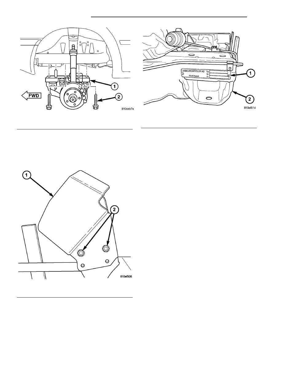
(18) Remove nuts and remove mount heat shield.

(Fig. 14)

(19) Remove stabilizer bar as necessary. (Refer to 2

-

SUSPENSION/FRONT/STABILIZER

BAR

-

REMOVAL)

(20) Remove steering gear. (Refer to 19 - STEER-

ING/GEAR - REMOVAL)

(21) Using a sharp flat bladed tool, remove identi-

fication plate. (Fig. 15)

INSTALLATION

(1) Using a suitable RTV sealant, attach identifica-

tion plate to engine cradle.

(2) Install steering gear onto engine cradle. (Refer

to 19 - STEERING/GEAR - INSTALLATION)

NOTE: Steering gear must be torqued in a three
step procedure below.

(3) Tighten steering gear bolts in three stages as

follows.

1. Tighten to 25 N·m (18 ft. lbs.)
2. Then tighten to 45 N·m (33 ft. lbs.)
3. Then tighten bolts an additional 90°.
(4) Install stabilizer bar. (Refer to 2 - SUSPEN-

SION/FRONT/STABILIZER BAR - INSTALLATION)

(5) Install heat shield and nuts.
(6) Install jounce bumpers and install nuts.
(7) Install support clips and brake lines.
(8) Raise engine cradle into place and install bolts.
(9) Tighten bolts to 125 N·m (92 ft. lbs.).
(10) Connect brake lines at couplings and tighten

to 14 N·m (10 ft. lbs.).

(11) Position power steering hose and install sup-

port bracket bolt.

(12) Install both power steering hoses at steering

gear. (Refer to 19 - STEERING/PUMP/HOSES -
INSTALLATION)

(13) Connect steering shaft to gear and install the

lower pinch bolt.

(14) Tighten lower pinch bolt to 24 N·m (18 ft.

lbs.).

(15) Install new tie straps holding transmission

harness to cradle.

(16) Install front spring. (Refer to 2 - SUSPEN-

SION/FRONT/SPRING - INSTALLATION)

(17) Install engine mount nuts and tighten to 45

N·m (33 ft. lbs.).

Fig. 13 ENGINE CRADLE BOLTS

1 - ENGINE CRADLE
2 - CRADLE BOLTS (4 PER SIDE)

Fig. 14 HEAT SHIELD

1 - HEAT SHIELD
2 - NUTS

Fig. 15 IDENTIFICATION PLATE

1 - IDENTIFICATION PLATE
2 - ENGINE CRADLE

13 - 10

FRAME & BUMPERS

VA

(18) Install calipers. (Refer to 5 - BRAKES/HY-

DRAULIC/MECHANICAL/DISC BRAKE CALIPERS
- INSTALLATION)

(19) Install new tie straps holding wheel speed

sensors and brake pad wear sensors wire harness to
cradle.

(20) Check and align vehicle to specifications.

(Refer to 2 - SUSPENSION/WHEEL ALIGNMENT -
STANDARD PROCEDURE)

REAR CROSSMEMBER -
TRANSMISSION

REMOVAL

(1) Raise

and

support

the

vehicle.

(Refer

to

LUBRICATION

&

MAINTENANCE/HOISTING

-

STANDARD PROCEDURE)

(2) Support transmission with a suitable lifting

device.

(3) Remove the bolts/nuts and remove transmis-

sion mount cover. (Fig. 16)

(4) Remove crossmember nuts and crossmember.

INSTALLATION

(1) Install crossmember and install nuts.
(2) Tighten crossmember nut to 45 N·m (33 ft.

lbs.).

(3) Remove transmission support.
(4) Install transmission mount bracket.
(5) Install

transmission

mount

bolts/nuts

and

tighten to 45 N·m (33 ft. lbs.).

TRAILER HITCH

REMOVAL

(1) Disconnect and isolate battery negative cable.
(2) Raise

and

support

the

vehicle.

(Refer

to

LUBRICATION

&

MAINTENANCE/HOISTING

-

STANDARD PROCEDURE)

(3) Disconnect electrical connector. (Fig. 17)

Fig. 16 TRANSMISSION CROSSMEMBER

1 - TRANSMISSION MOUNT BOLTS (2)
2 - TRANSMISSION MOUNT COVER
3 - TRANSMISSION CROSSMEMBER NUTS (4)
4 - TRANSMISSION MOUNT NUTS (2)
5 - TRANSMISSION SUPPORT
6 - CROSSMEMBER
7 - TRANSMISSION MOUNT

VA

FRAME & BUMPERS

13 - 11

WARNING: Microencapsulated bolts and self-lock-
ing nuts may only be used once. If you use
microencapsulated bolt or self-locking nuts more
than once, the self-locking function is rendered
useless. The trailer hitch may become detached
from the vehicle, possibly resulting in a serious risk
of injury and/or damage to property, including dam-
age to the vehicle.

(4) Remove and discard microencapsulated angle

bracket bolts/nuts. (Fig. 18)

(5) Support hitch and remove frame bolts. (Fig. 19)
(6) Lower hitch.

INSTALLATION

WARNING: Do not oil or grease the bolts and nuts.
if the bolts and nuts are greased, the trailer hitch
may become detached from the vehicle, possibly
resulting in a serious risk of injury and/or damage
to property, including damage to the vehicle.

(1) Raise hitch into position.
(2) Install the mounting plate and new frame

bolts/nuts and hand tighten bolts.

Fig. 17 TRAILER HITCH ELECTRICAL CONNECTION

1 - TRAILER CONNECTION SOCKET
2 - ELECTRICAL CONNECTOR TAB
3 - SUPPORT BRACKET
4 - ELECTRICAL CONNECTOR
5 - SCREWS (4)

Fig. 18 TRAILER HITCH MOUNTING

1 - LOCK NUTS (8)
2 - MOUNTING PLATE
3 - BOLTS (8)
4 - ANGLE BRACKETS (2)
5 - BOLTS (4)
6 - HITCH
7 - BRACKET BOLTS/NUTS

Fig. 19 TRAILER HITCH

1 - FRAME BOLTS (8)
2 - MOUNTING PLATES (2)
3 - LOCK NUTS (8)
4 - TRAILER HITCH
5 - BRACKET TO STEP BOLTS (4)
6 - ANGLE BRACKETS (2)
7 - BRACKET BOLTS (4)

13 - 12

FRAME & BUMPERS

VA

WARNING: Microencapsulated bolts and self-lock-
ing nuts may only be used once. If you use
microencapsulated bolt or self-locking nuts more
than once, the self-locking function is rendered
useless. The trailer hitch may become detached
from the vehicle, possibly resulting in a serious risk
of injury and/or damage to property, including dam-
age to the vehicle.

(3) Install the angle bracket microencapsulated

bolts/nuts and hand tighten.

(4) Align trailer hitch.
(5) Tighten the frame mounting bolts to 110 N·m

(81 ft. lbs.).

(6) Tighten microencapsulated angle bracket bolts

to 50 N·m (37 ft. lbs.)

(7) Connect trailer socket electrical connector.

VA

FRAME & BUMPERS

13 - 13


Content   ..  239  240  241  242   ..