Dodge Sprinter. Manual - part 89


  Index      Dodge     Dodge Sprinter / Mercedes-Benz - service repair manual 2006 year


Search            


Content   ..  87  88  89  90   ..


Dodge Sprinter. Manual - part 89


WIPER BLADE

DESCRIPTION

Each wiper blade is secured by an integral latching

pivot block to the hook formation on the tip of the
wiper arm, and rests on the glass near the base of
the windshield when the wipers are not in operation
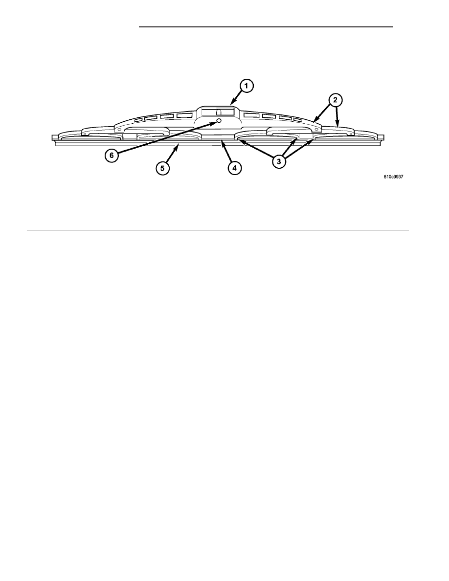
(Fig. 26). The wiper blade consists of the following
components:

• Superstructure - The superstructure includes

several stamped steel bridges and links with claw
formations that grip the wiper blade element. Also
included in this unit is the latching, molded plastic
pivot block that secures the superstructure to the
wiper arm. All of the metal components of the wiper
blade have a satin black finish applied.

• Element - The wiper element or squeegee is the

resilient rubber member of the wiper blade that con-
tacts the glass.

• Flexor - The flexor is a rigid metal component

running along the length of the wiper element on
each side, where it is gripped by the claws of the
superstructure.

All Sprinter models have unequal length wiper

blades with non-replaceable rubber elements (squee-
gees). The left (driver) side wiper blade is 60.0 centi-
meters (23.5 inches), and the right (passenger) side
wiper blade is 55.0 centimeter (21.5 inches). These
wiper blades also include an anti-lift feature. The
wiper blades cannot be adjusted or repaired. If faulty,
worn, or damaged the entire wiper blade unit must
be replaced.

OPERATION

The wiper blades are moved back and forth across

the glass by the wiper arms when the wipers are
being operated. The wiper blade superstructure is

the flexible frame that grips the wiper blade element
and evenly distributes the force of the spring-loaded
wiper arm along the length of the element. The com-
bination of the wiper arm force and the flexibility of
the superstructure makes the element conform to
and maintain proper contact with the glass, even as
the blade is moved over the varied curvature that
may be encountered across the glass surface. The
wiper element flexor provides the claws of the blade
superstructure with a rigid, yet flexible component
on the element which can be gripped. The rubber ele-
ment is designed to be stiff enough to maintain an
even cleaning edge as it is drawn across the glass,
but resilient enough to conform to the glass surface
and flip from one cleaning edge to the other each
time the wiper blade changes directions.

REMOVAL

NOTE: The wiper arms and wiper blades for this
model are both unequal in length, with the longer
arm and blade being installed on the left (driver)
side of the windshield.

(1) Turn the wiper control knob on the end of the

multi-function switch control stalk to the On posi-
tion. Cycle the wiper blades to a convenient working
location on the windshield by turning the ignition
switch to the On and Off positions.

(2) Lift the wiper arm to raise the wiper blade and

element off of the glass, until the wiper arm hinge is
in its over-center position.

(3) To remove the wiper blade from the wiper arm,

depress the pivot block latch release tab under the
tip of the arm and slide the blade away from the tip

Fig. 26 Wiper Blade

1 - PIVOT BLOCK

4 - FLEXOR

2 - SUPERSTRUCTURE

5 - ELEMENT

3 - CLAWS

6 - PIVOT PIN

8R - 26

WIPERS/WASHERS

VA

towards the pivot end of the arm far enough to dis-
engage the pivot block from the hook formation on
the end of the arm (Fig. 27).

(4) Extract the hook formation on the tip of the

wiper arm from the opening in the wiper blade
superstructure ahead of the wiper blade pivot block/
latch unit.

CAUTION: Do not allow the wiper arm to spring
back against the glass without the wiper blade in
place or the glass may be damaged.

(5) Gently lower the wiper arm tip onto the glass.

INSTALLATION

NOTE: The wiper arms and wiper blades for this
model are both unequal in length, with the longer
arm and blade being installed on the left (driver)
side of the windshield.

(1) Lift the wiper arm off of the windshield glass,

until the wiper arm hinge is in its over-center posi-
tion.

(2) Position the wiper blade near the hook forma-

tion on the tip of the arm.

(3) Insert the hook formation on the tip of the

wiper arm through the opening in the wiper blade
superstructure ahead of the wiper blade pivot block/
latch unit far enough to engage the pivot block with
the hook (Fig. 27).

(4) Slide the wiper blade pivot block/latch up into

the hook formation on the tip of the wiper arm until
the latch release tab snaps into its locked position.
Latch engagement will be accompanied by an audible
click.

(5) Gently lower the wiper blade onto the glass.

Fig. 27 Wiper Blade Remove/Install

1 - HOOK
2 - WIPER BLADE
3 - WIPER ARM
4 - RELEASE TAB

VA

WIPERS/WASHERS

8R - 27

WIPER LINKAGE

DESCRIPTION

The wiper linkage and pivots are concealed within

the engine compartment below the cowl top panel
(Fig. 28). The ends of the wiper pivot shafts that pro-
trude through dedicated openings in the cowl top
panel to drive the wiper arms and blades are the
only visible components of the wiper linkage module.
The wiper linkage module consists of the following
major components:

• Linkage - The two wiper drive links are each

constructed of stamped steel. The left (driver) side
drive link has a plastic socket-type bushing in one
end, and a plastic sleeve-type bushing in the other
end. The socket bushing is snap-fit over the ball stud
on the left pivot crank arm, while the sleeve bushing
is fit over the longer ball stud on the wiper motor
crank arm. The right (passenger) side drive link has
a plastic socket-type bushing on each end. One end of
this drive link is snap-fit over the exposed end of the
longer ball stud on the wiper motor crank arm and
captures the sleeve bushing end of the left drive link
beneath it, while the other end is snap-fit over the
ball stud on the right pivot crank arm.

• Module Bracket - The linkage module bracket

consists of a long tubular steel main member that is
crimped to a molded plastic pivot bracket at each end
where the wiper pivots are secured. A stamped steel
mounting plate for the wiper motor is secured with
welds near the center of the main member and is
then secured with screws to the underside of the cowl
top panel.

• Motor Crank Arm - The wiper motor crank

arm is a stamped steel unit with a round hole on the
driven end that is secured to the wiper motor output

shaft with a nut, and a long ball stud secured to the
drive end.

• Pivot - The two molded plastic wiper pivot

brackets are secured to the ends of the linkage mod-
ule bracket tubular member. The crank arms that
extend from the bottom of the pivot shafts each have
a ball stud on their end. The upper end of each pivot
shaft where the wiper arms will be fastened each is
tapered and externally serrated with a threaded stud
at the top where the wiper arms are secured by a
nut. Each pivot shaft operates within a housing
formed in the pivot bracket featuring a large external
flange near its center and external threads near the
top. The pivot housings are secured to the outer sur-
face of the cowl top panel by a large washer and a
nut threaded onto the outside of the housing where it
protrudes through the cowl top.

The wiper linkage module cannot be adjusted or

repaired. If any component of the linkage module is
faulty or damaged, the entire wiper linkage module
unit must be replaced.

OPERATION

The wiper linkage operation is controlled by the

output of the wiper motor through the wiper motor
crank arm. The wiper motor crank arm, the two
wiper drive links, and the two wiper pivots mechan-
ically convert the rotary output of the wiper motor to
the back and forth wiping motion of the wiper arms
and blades on the glass.

REMOVAL

(1) Disconnect and isolate the battery negative

cable.

Fig. 28 Wiper Linkage Module

1 - PIVOT SHAFT (2)

4 - PIVOT CRANK ARM (2)

2 - PIVOT SHAFT HOUSING (2)

5 - DRIVE LINK (2)

3 - MODULE BRACKET

6 - MOTOR CRANK ARM

8R - 28

WIPERS/WASHERS

VA

(2) Remove the wiper arms from the wiper pivots.

(Refer to 8 - ELECTRICAL/WIPERS/WASHERS/
WIPER ARM - REMOVAL).

(3) Remove the five nuts that secure the ventila-

tion housing to the dash panel and the underside of
the cowl top panel (Fig. 29).

VA

WIPERS/WASHERS

8R - 29


Content   ..  87  88  89  90   ..