Dodge Sprinter. Manual - part 76


  Index      Dodge     Dodge Sprinter / Mercedes-Benz - service repair manual 2006 year


Search            


Content   ..  74  75  76  77   ..


Dodge Sprinter. Manual - part 76


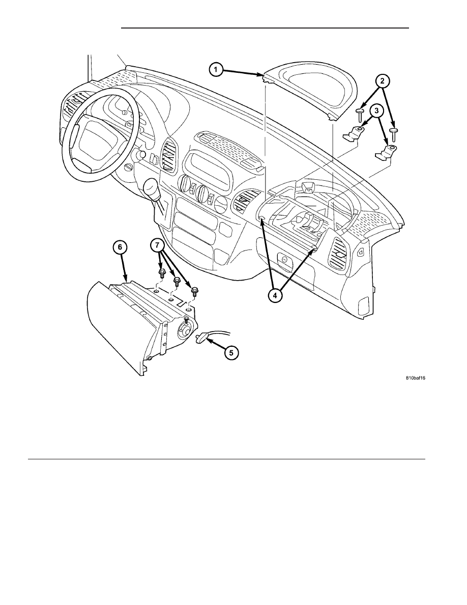
(3) Remove the two screws that secure the passen-

ger airbag door upper clips to the instrument panel
base trim.

(4) Remove the three screws that secure the flange

of the passenger airbag housing to the bracket on the
instrument panel structural support.

(5) Pull the passenger airbag unit rearward to dis-

engage the airbag door from the lower clips and far
enough to access the electrical connection on the
right end of the unit.

CAUTION: Do not pull on the wires to disengage
the connector from the passenger airbag inflator
connector receptacle. Improper removal of the con-
nector insulator can result in damage to the airbag
circuits or the connector insulator.

(6) The vehicle wire harness connector is a tight

snap-fit into the airbag inflator connector receptacle,
which is located on the right end of the passenger
airbag housing. Firmly grasp and pull or gently pry
on the connector insulator and pull the connector

Fig. 29 Passenger Airbag Remove/Install

1 - TRAY
2 - SCREW (2)
3 - UPPER CLIP (2)
4 - LOWER CLIP (2)
5 - CONNECTOR
6 - PASSENGER AIRBAG
7 - SCREW (3)

8O - 26

RESTRAINTS

VA

straight out from the inflator to disconnect it from
the receptacle.

(7) Remove the passenger airbag and airbag door

from the instrument panel as a unit.

INSTALLATION

The following procedure is for replacement of a

faulty or damaged passenger airbag. If the airbag is
faulty or damaged, but not deployed, review the rec-
ommended procedures for handling non-deployed
supplemental restraints. (Refer to 8 - ELECTRICAL/
RESTRAINTS - STANDARD PROCEDURE - HAN-
DLING

NON-DEPLOYED

SUPPLEMENTAL

RESTRAINTS). If the passenger airbag has been
deployed, review the recommended procedures for
service after a supplemental restraint deployment
before removing the airbag from the vehicle. (Refer to
8 - ELECTRICAL/RESTRAINTS - STANDARD PRO-
CEDURE - SERVICE AFTER A SUPPLEMENTAL
RESTRAINT DEPLOYMENT).

WARNING: To avoid personal injury or death, on
vehicles equipped with airbags, disable the supple-
mental

restraint

system

before

attempting

any

steering wheel, steering column, airbag, seat belt
tensioner, impact sensor, or instrument panel com-
ponent diagnosis or service. Disconnect and isolate
the battery negative (ground) cable, then wait two
minutes for the system capacitor to discharge
before performing further diagnosis or service. This
is the only sure way to disable the supplemental
restraint system. Failure to take the proper precau-
tions could result in accidental airbag deployment.

WARNING: To avoid personal injury or death, use
extreme care to prevent any foreign material from
entering

the

passenger

airbag,

or

becoming

entrapped between the passenger airbag cushion
and the passenger airbag door. Failure to observe
this warning could result in occupant injuries upon
airbag deployment.

WARNING: To avoid personal injury or death, the
passenger airbag door must never be painted.
Replacement passenger airbags are serviced with
doors in the original colors. Paint may change the
way in which the material of the airbag door
responds to an airbag deployment. Failure to
observe this warning could result in occupant inju-
ries upon airbag deployment.

(1) Carefully position the passenger airbag and

airbag door unit to the instrument panel (Fig. 29).

(2) When installing the passenger airbag, recon-

nect the vehicle wire harness connector to the airbag
inflator connector receptacle by pressing straight in
on the connector. You can be certain that the connec-

tor is fully engaged by listening carefully for a dis-
tinct, audible click as the connector snaps into place.

(3) Push the passenger airbag unit forward far

enough to engage the lower edge of the airbag door
with the two lower clips in the instrument panel.

(4) Install and tighten the two screws that secure

the flange of the passenger airbag housing to the
bracket on the instrument panel structural support.
Tighten the screws to 10 N·m (89 in. lbs.).

(5) Install and tighten the two screws that secure

the passenger airbag door upper clips to the instru-
ment panel base trim. Tighten the screws to 2 N·m
(18 in. lbs.).

(6) Reinstall the instrument panel top cover tray

onto the instrument panel. (Refer to 23 - BODY/IN-
STRUMENT PANEL/INSTRUMENT PANEL TOP
COVER - TRAY - INSTALLATION).

(7) Do not reconnect the battery negative cable at

this time. The supplemental restraint system verifi-
cation test procedure should be performed following
service of any supplemental restraint system compo-
nent. (Refer to 8 - ELECTRICAL/RESTRAINTS -
STANDARD PROCEDURE - VERIFICATION TEST).

PASSENGER AIRBAG
BRACKET

REMOVAL

WARNING: To avoid personal injury or death, on
vehicles equipped with airbags, disable the supple-
mental

restraint

system

before

attempting

any

steering wheel, steering column, airbag, seat belt
tensioner, impact sensor, or instrument panel com-
ponent diagnosis or service. Disconnect and isolate
the battery negative (ground) cable, then wait two
minutes for the system capacitor to discharge
before performing further diagnosis or service. This
is the only sure way to disable the supplemental
restraint system. Failure to take the proper precau-
tions could result in accidental airbag deployment.

(1) Remove the passenger airbag from the instru-

ment

panel.

(Refer

to

8

-

ELECTRICAL/RE-

STRAINTS/PASSENGER AIRBAG - REMOVAL).

(2) Remove the four screws that secure the passen-

ger airbag bracket to the instrument panel structural
support (Fig. 30).

VA

RESTRAINTS

8O - 27

(3) Remove the passenger airbag bracket from the

instrument panel structural support.

INSTALLATION

WARNING: To avoid personal injury or death, on
vehicles equipped with airbags, disable the supple-
mental

restraint

system

before

attempting

any

steering wheel, steering column, airbag, seat belt
tensioner, impact sensor, or instrument panel com-
ponent diagnosis or service. Disconnect and isolate
the battery negative (ground) cable, then wait two
minutes for the system capacitor to discharge
before performing further diagnosis or service. This
is the only sure way to disable the supplemental
restraint system. Failure to take the proper precau-
tions could result in accidental airbag deployment.

(1) Position the passenger airbag bracket onto the

instrument panel structural support (Fig. 30).

(2) Install and tighten the four screws that secure

the passenger airbag bracket to the instrument panel
structural support. Tighten the screws to 10 N·m (89
in. lbs.).

(3) Reinstall the passenger airbag into the instru-

ment

panel.

(Refer

to

8

-

ELECTRICAL/RE-

STRAINTS/PASSENGER

AIRBAG

-

INSTALLATION).

REAR SEAT BELT & RETRAC-
TOR

REMOVAL

WARNING: To avoid personal injury or death, during
and

following

any

seat

belt

service,

carefully

inspect all seat belts, buckles, mounting hardware,

retractors, and anchors for proper installation, oper-
ation, or damage. Replace any belt that is cut,
frayed, or torn. Straighten any belt that is twisted.
Tighten any loose fasteners. Replace any belt that
has a damaged or inoperative buckle or retractor.
Replace any belt that has a bent or damaged latch
plate or anchor plate. Never attempt to repair a seat
belt component. Always replace damaged or faulty
seat belt components with the correct, new and
unused

replacement

parts

listed

in

the

DaimlerChrysler Mopar Parts Catalog.

(1) Remove the rear bench seat containing the rear

seat belt and retractor unit to be serviced from the
vehicle.

(2) Lift the seat belt webbing to access and remove

the plastic push pin fastener that secures the rear
seat belt turning loop trim cover to the turning loop
bracket at the top of the seat back (Fig. 31).

(3) Remove the turning loop trim cover from the

turning loop bracket.

(4) Remove the push nut at the back of the turn-

ing loop bracket that secures the pin on which the
two turning loops pivot (Fig. 32).

Fig. 30 Passenger Airbag Bracket Remove/Install

1 - BRACKET
2 - STRUCTURAL SUPPORT
3 - SCREW (4)

Fig. 31 Turning Loop Trim Cover

1 - TRIM COVER
2 - SEAT BELT
3 - RETAINER
4 - REAR SEAT BACK

8O - 28

RESTRAINTS

VA

(5) Remove the pin and the two turning loops from

the turning loop bracket.

(6) For a left outboard seating position only,

unsnap and remove the plastic cover from the screw
that secures the rear seat belt lower anchor to the
left outboard side of the seat frame (Fig. 33).

(7) Remove the plastic shield from the back of the

rear seat. (Refer to 23 - BODY/SEATS/REAR SEAT
BACK SHIELD - REMOVAL).

(8) Remove the screw that secures the rear seat

belt lower anchor to the rear seat cushion frame (Fig.
33) or (Fig. 34).

(9) Pull the rear seat belt and lower anchor

through the turning loop trim cover and the turning
loop bracket.

(10) Remove the screw that secures the rear seat

belt retractor to the bracket on the rear seat cushion
frame (Fig. 35).

(11) Remove the rear seat belt and retractor unit

from the bracket on the rear seat cushion frame.

Fig. 32 Rear Seat Belt Turning Loop

1 - TURNING LOOP (2)
2 - PUSH NUT
3 - BRACKET
4 - PIN
5 - REAR SEAT BACK
6 - SEAT BELT

Fig. 33 Left Outboard Rear Seat Belt Lower Anchor

1 - REAR SEAT CUSHION TRIM
2 - REAR SEAT BACK TRIM
3 - SCREW AND COVER
4 - REAR SEAT BELT LOWER ANCHOR

Fig. 34 Right Outboard or Center Rear Seat Belt

Lower Anchor

1 - REAR SEAT CUSHION FRAME
2 - SCREW
3 - REAR SEAT BELT LOWER ANCHOR

Fig. 35 Rear Seat Belt Retractor

1 - RETRACTOR
2 - REAR SEAT CUSHION FRAME
3 - SCREW

VA

RESTRAINTS

8O - 29


Content   ..  74  75  76  77   ..