Dodge Sprinter. Manual - part 60


  Index      Dodge     Dodge Sprinter / Mercedes-Benz - service repair manual 2006 year


Search            


Content   ..  58  59  60  61   ..


Dodge Sprinter. Manual - part 60


seat riser, a fog lamp switch installed in the cluster
bezel on the instrument panel outboard of the steer-
ing column, and a fog lamp bulb installed in each of
the two front lamp units. The front fog lamps have a
path to ground at all times through their connection
to the vehicle wire harness. The headlamp switch cir-
cuitry of the left (lighting) control stalk of the multi-
function switch controls front fog lamp operation by
providing battery current to the front fog lamp relay
only when the low beam headlamps are selected. The
fog lamp switch controls front fog lamp operation by
energizing or de-energizing the front fog lamp relay
control coil.

HAZARD WARNING LAMPS

With the hazard switch in the On position, the

hazard switch button illuminates and the right and
left turn signal indicators as well as the right and
left turn signal lamps begin to flash on and off. When
the hazard warning system is activated, the hazard
switch circuitry within the multi-function switch and
the wipers, turn signals and engine start control
module electronic circuitry within the fuse block will
repeatedly energize and de-energize the turn signal
relay located in the fuse block. The turn signal relay
switches battery current from a fused B(+) fuse in
the fuse block to the turn signal indicators and the
turn signal lamps. The flashing of the hazard switch
button illumination lamp is also controlled by the
output from the turn signal relay.

HEADLAMPS

The headlamp system includes the exterior lighting

switches integral to the left (lighting) control stalk of
the multi-function switch as well as the low and high
beam bulbs installed in the right and left front lamp
units (Fig. 1). The headlamp bulbs have a path to
ground at all times through the vehicle wire harness.
The exterior lighting switches control headlamp oper-
ation by providing battery current to the selected low
or high beam bulbs. Each front lamp unit includes
two integral adjustment screws to be used for static
horizontal and vertical aiming of the headlamp beam
reflectors.

HEADLAMP LEVELING

The headlamp leveling system includes a leveling

actuator motor integral to each front lamp unit, and
a rotary thumbwheel actuated headlamp leveling
switch in the cluster bezel on the instrument panel
outboard of the steering column. The headlamp lev-
eling system allows the headlamp beam reflectors to
be adjusted to one of four vertical positions to com-
pensate for changes in inclination caused by the load-
ing of the vehicle suspension. The actuator motors
are mechanically connected through an integral
pushrod to an adjustable headlamp reflector. The
headlamp leveling switch is a resistor multiplexed
unit that provides one of four voltage outputs to the
headlamp leveling motors. The headlamp leveling
motors will move the headlamps to the selected posi-
tion based upon the voltage input received from the
switch. The headlamp leveling motors and switch
have a path to ground at all times. The headlamp
leveling components operate on battery current
received through the park lamps circuit so that the
system will only operate when the exterior lighting is
turned on.

PARK LAMPS

The park lamps system includes the exterior light-

ing switches integral to the left (lighting) control
stalk of the multi-function switch (Fig. 1), the front
park/side marker lamps, the front position lamps, the
rear park lamps, the rear side marker lamps, the
optional clearance lamps, and the license plate
lamps. Each of these lamps are provided with a path
to ground at all times through the vehicle wire har-
ness. The exterior lighting switches control the park
lamp operation by providing battery current through
the park lamps circuit to the appropriate lamp bulbs.

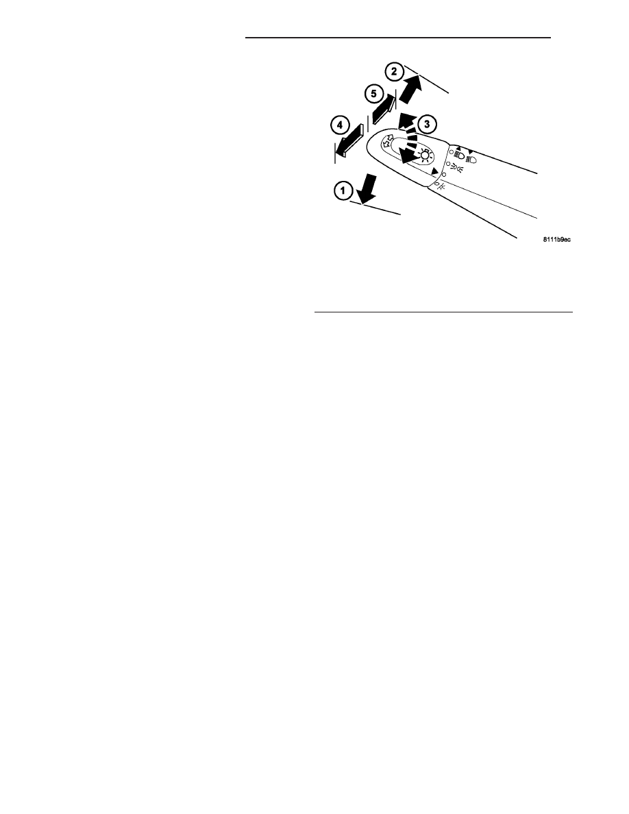
Fig. 1 Lighting Switch

1 - LEFT TURN SIGNAL
2 - RIGHT TURN SIGNAL
3 -EXTERIOR LIGHTING
4 - BEAM SELECT (DIMMER)
5 - OPTICAL HORN

8L - 4

LAMPS/LIGHTING - EXTERIOR

VA

TURN SIGNAL LAMPS

When the left (lighting) control stalk of the multi-

function switch is activated (Fig. 1), the turn signal
system illuminates the selected right or left turn sig-
nal indicator and the turn signal lamps begin to
flash. The turn signal lamps include a bulb integral
to each front lamp unit and each tail lamp unit, as
well as a repeater lamp bulb located on each front
fender above the front wheels. When the turn signal
system is activated, the turn signal switch circuitry
within the multi-function switch and the electronic
circuitry of the wipers, turn signals and engine start
control module within the fuse block will repeatedly
energize and de-energize the turn signal relay
located in the fuse block. The turn signal relay
switches battery current from a fused ignition switch
output fuse in the fuse block to the appropriate turn
signal indicator and turn signal lamps.

The ElectroMechanical Instrument Cluster (EMIC)

contactless relay will generate repetitive, audible
turn signal “click” sounds to emulate the sounds of a
conventional electro-mechanical turn signal flasher
at one of two rates to coincide with the flashing of
the turn signals. The slow rate emulates normal turn
signal operation, while the fast rate emulates “bulb
out” turn signal operation.

SPECIFICATIONS - LAMPS / LIGHTING - EXTE-
RIOR

BULB SPECIFICATIONS

LAMP

BULB

Backup

P21W - 12V 21W

Brake & Rear Park

P21/5W - 12V 21/5W

Center High Mounted
Stop

P21W - 12V 21W

Clearance

W3W - 12V 3W

Front Fog

H1 - 12V 55W

Front Position

W5W - 12V 5W

Front Turn, Park & Side
Marker

3457 NA - 12V 28/7.5W
Amber Glass

Low Beam Headlamp

H7 - 12V 55W

High Beam Headlamp

H1 - 12V 55W

License Plate

C5W - 12V 5W

Rear Side Marker

R5W - 12V 5W

Rear Turn

P21W - 12V 21W

Side Repeater

W5W - 12V 3W

BACKUP LAMP BULB

REMOVAL

(1) Disconnect and isolate the battery negative

cable.

(2) If the vehicle is so equipped, remove the trim

from the inside of the right or left rear corner pillar.

(3) From inside the vehicle, use hand pressure to

push the two latch tabs toward the center of the tail
lamp unit socket plate and pull the socket plate
straight out from the inner rear pillar (Fig. 2).

(4) Pull the socket plate away from the inner rear

pillar far enough to access the backup lamp bulb
(Fig. 3).

Fig. 2 Tail Lamp Socket Plate Remove/Install

1 - SOCKET PLATE
2 - INNER REAR PILLAR
3 - LATCH TAB (2)

VA

LAMPS/LIGHTING - EXTERIOR

8L - 5

(5) Remove the backup lamp bulb from the tail

lamp socket plate.

INSTALLATION

(1) Install the backup lamp bulb into the tail lamp

socket plate (Fig. 3).

(2) Align the socket plate with the mounting hole

in the inner rear pillar.

(3) Using hand pressure, push the socket plate

gently and evenly into the inner rear pillar mounting
hole until both latch tabs are fully engaged (Fig. 2).

(4) If the vehicle is so equipped, reinstall the trim

onto the inside of the right or left rear corner pillar.

(5) Reconnect the battery negative cable.

BRAKE LAMP SWITCH

REMOVAL

WARNING: To avoid personal injury or death, on
vehicles equipped with airbags, disable the supple-
mental

restraint

system

before

attempting

any

steering wheel, steering column, airbag, seat belt
tensioner, or instrument panel component diagno-
sis or service. Disconnect and isolate the battery
negative (ground) cable, then wait two minutes for
the system capacitor to discharge before perform-
ing further diagnosis or service. This is the only
sure way to disable the supplemental restraint sys-
tem. Failure to take the proper precautions could
result in accidental airbag deployment.

(1) Disconnect and isolate the battery negative

cable.

(2) Locate the brake lamp switch on the pedal

bracket underneath the instrument panel (Fig. 4).

(3) Depress the locking tab on the brake lamp

switch body behind the pedal bracket and rotate the
switch counterclockwise about 30 degrees (Fig. 5).

(4) Pull the switch forward in the vehicle far

enough to disengage the switch plunger from the
mounting hole in the pedal bracket.

(5) Disconnect the vehicle wire harness from the

brake lamp switch connector receptacle.

(6) Remove the brake lamp switch from the vehi-

cle.

Fig. 3 Tail Lamp Bulb Remove/Install

1 - BRAKE/PARK LAMP BULB
2 - BACKUP LAMP BULB
3 - TURN SIGNAL LAMP BULB
4 - SIDE MARKER LAMP BULB
5 - TAIL LAMP SOCKET PLATE

Fig. 4 Brake Lamp Switch Location

1 - PEDAL BRACKET
2 - BRAKE LAMP SWITCH
3 - BRAKE PEDAL

Fig. 5 Brake Lamp Switch Remove/Install

1 - PEDAL BRACKET
2 - PLUNGER
3 - BRAKE LAMP SWITCH
4 - CONNECTOR RECEPTACLE
5 - LOCKING TAB

8L - 6

LAMPS/LIGHTING - EXTERIOR

VA

INSTALLATION

WARNING: To avoid personal injury or death, on
vehicles equipped with airbags, disable the supple-
mental

restraint

system

before

attempting

any

steering wheel, steering column, airbag, seat belt
tensioner, or instrument panel component diagno-
sis or service. Disconnect and isolate the battery
negative (ground) cable, then wait two minutes for
the system capacitor to discharge before perform-
ing further diagnosis or service. This is the only
sure way to disable the supplemental restraint sys-
tem. Failure to take the proper precautions could
result in accidental airbag deployment.

(1) Pull the plunger of the brake lamp switch out-

ward from the switch body to its travel limit (Fig. 5).

(2) Reconnect the vehicle wire harness to the

brake lamp switch connector receptacle.

(3) Depress and hold the brake pedal in the

depressed position until the brake lamp switch
installation is completed (Fig. 4).

(4) Insert the brake lamp switch plunger through

the mounting hole from behind until the switch lock-
ing collar is fully seated against the pedal bracket.

(5) Rotate the brake lamp switch clockwise until

the locking tab on the switch body fully engages the
pedal bracket. Full locking tab engagement will be
accompanied by an audible click.

NOTE: Do not pull the brake pedal upwards as this
will adjust the switch plunger to an incorrect posi-
tion. The switch is properly adjusted when the
switch plunger is just contacting (no gap) the brake
pedal arm with the pedal in the relaxed (released)
position.

(6) Release the brake pedal from its depressed

position to automatically adjust the brake lamp
switch plunger.

(7) Reconnect the battery negative cable.

ADJUSTMENTS

ADJUSTMENT

WARNING: To avoid personal injury or death, on
vehicles equipped with airbags, disable the supple-
mental

restraint

system

before

attempting

any

steering wheel, steering column, airbag, seat belt
tensioner, or instrument panel component diagno-
sis or service. Disconnect and isolate the battery
negative (ground) cable, then wait two minutes for
the system capacitor to discharge before perform-
ing further diagnosis or service. This is the only
sure way to disable the supplemental restraint sys-

tem. Failure to take the proper precautions could
result in accidental airbag deployment.

(1) Disconnect and isolate the battery negative

cable.

(2) Depress and hold the brake pedal in the

depressed position until the brake lamp switch
adjustment is completed.

(3) Pull the plunger of the brake lamp switch out-

ward from the switch body to its travel limit.

NOTE: Do not pull the brake pedal upwards as this
will adjust the switch plunger to an incorrect posi-
tion. The switch is properly adjusted when the
switch plunger is just contacting (no gap) the brake
pedal arm with the pedal in the relaxed (released)
position.

(4) Release the brake pedal from its depressed

position to automatically adjust the brake lamp
switch plunger.

BRAKE / PARK LAMP BULB

REMOVAL

(1) Disconnect and isolate the battery negative

cable.

(2) If the vehicle is so equipped, remove the trim

from the inside of the right or left rear corner pillar.

(3) From inside the vehicle, use hand pressure to

push the two latch tabs toward the center of the tail
lamp unit socket plate and pull the socket plate
straight out from the inner rear pillar (Fig. 6).

VA

LAMPS/LIGHTING - EXTERIOR

8L - 7


Content   ..  58  59  60  61   ..