Dodge Sprinter. Manual - part 7


  Index      Dodge     Dodge Sprinter / Mercedes-Benz - service repair manual 2006 year


Search            


Content   ..  5  6  7  8   ..


Dodge Sprinter. Manual - part 7


STABILIZER LINK

REMOVAL

(1) Raise and support the vehicle.
(2) Remove the stabilizer links at the bar (Fig. 4).
(3) Remove the stabilizer link at the frame.

INSTALLATION

(1) Install the stabilizer bar to the stabilizer links

and tighten to 95 N·m (60 ft. lbs.) (Fig. 4).

(2) Lower the vehicle.
(3) Install the stabilizer link to the frame. Tighten

to 95 N·m (60 ft. lbs.).

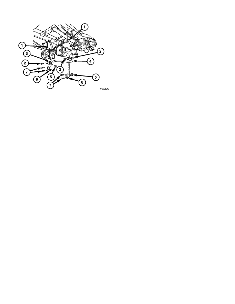
Fig. 5 SWAY BAR WITH DUAL REAR WHEELS

(DRW)

1 - STABILIZER LINK
2 - SWAY BRA BOLT
3 - SWAY BAR NUT
4 - SWAY BAR
5 - RUBBER MOUNT
6 - SWAY BAR CLAMP
7 - CLAMP MOUNTING BOLTS

2 - 16

REAR

VA

WHEEL ALIGNMENT

TABLE OF CONTENTS

page

page

WHEEL ALIGNMENT

DESCRIPTION

. . . . . . . . . . . . . . . . . . . . . . . . 17

DIAGNOSIS AND TESTING - PRE-ALIGNMENT

INSPECTION

. . . . . . . . . . . . . . . . . . . . . . . . . 17

STANDARD PROCEDURE - TOE

ADJUSTMENT

. . . . . . . . . . . . . . . . . . . . . . . . 18

SPECIFICATIONS

. . . . . . . . . . . . . . . . . . . . . 19

WHEEL ALIGNMENT

DESCRIPTION

NOTE: Camber and Caster are not adjustable on
this vehicle. (TOE ONLY).

NOTE: Suspension components with rubber/ure-
thane bushings should be tightened with the vehi-
cle at normal ride height. It is important to have the
springs supporting the weight of the vehicle when
the fasteners are torqued. If springs are not at their
normal ride position, vehicle ride comfort could be
affected and premature bushing wear may occur.

Wheel alignment involves the correct positioning of

the wheels in relation to the vehicle. The positioning
is accomplished through suspension and steering
linkage adjustments. An alignment is considered
essential for efficient steering, good directional stabil-
ity and to minimize tire wear. The most important
measurements of an alignment are caster, camber
and toe (Fig. 1).

CAUTION: Never attempt to modify suspension or
steering components by heating or bending.

DIAGNOSIS AND TESTING - PRE - ALIGNMENT
INSPECTION

Before starting wheel alignment, the following

inspection and necessary corrections must be com-
pleted. Refer to Suspension and Steering System
Diagnosis Chart below for additional information.

(1) Inspect tires for size, air pressure and tread

wear.

(2) Inspect front wheel bearings for wear.
(3) Inspect front wheels for excessive radial or lat-

eral runout and balance.

(4) Inspect ball studs, linkage pivot points and

steering gear for looseness, roughness or binding.

(5) Inspect suspension components for wear and

noise.

(6) Road test the vehicle.

Fig. 1 Wheel Alignment Measurements

1 - FRONT OF VEHICLE
2 - STEERING AXIS INCLINATION
3 - PIVOT POINT
4 - TOE-IN

VA

WHEEL ALIGNMENT

2 - 17

SUSPENSION AND STEERING SYSTEM DIAGNOSIS

CONDITION

POSSIBLE CAUSES

CORRECTION

FRONT END NOISE

1. Loose or worn wheel bearing.

1. Replace wheel bearing.

2. Loose or worn steering or sus-
pension components.

2. Tighten or replace components as nec-
essary.

3. Loose or worn steering or sus-
pension components.

3. Tighten or replace components as nec-
essary.

EXCESSIVE PLAY IN
STEERING

1. Loose or worn wheel bearing.

1. Replace wheel bearing.

2. Loose or worn steering or sus-
pension components.

2. Tighten or replace components as nec-
essary.

3. Loose or worn steering gear.

3. Replace steering gear.

FRONT WHEELS SHIMMY

1. Loose or worn wheel bearing.

1. Replace wheel bearing.

2. Loose or worn steering or sus-
pension components.

2. Tighten or replace components as nec-
essary.

3. Tires worn or out of balance.

3. Replace or balance tires.

4. Alignment.

4. Align vehicle to specifications.

VEHICLE INSTABILITY

1. Loose or worn wheel bearing.

1. Replace wheel bearing.

2. Loose or worn steering or sus-
pension components.

2. Tighten or replace components as nec-
essary.

3. Tire pressure.

3. Adjust tire pressure.

4. Alignment.

4. Align vehicle to specifications.

EXCESSIVE STEERING
EFFORT

1. Loose or worn steering gear.

1. Replace steering gear.

2. Column coupler binding.

2. Replace coupler.

3. Tire pressure.

3. Adjust tire pressure.

4. Alignment.

4. Align vehicle to specifications.

VEHICLE PULLS TO ONE
SIDE

1. Tire pressure.

1. Adjust tire pressure.

2. Tire.

2. Criss-Cross Front Tires.

3. Alignment.

3. Align vehicle to specifications.

4. Loose or worn steering or sus-
pension components.

4. Tighten or replace components as nec-
essary.

5. Radial tire lead.

5. Rotate or replace tire as necessary.

6. Brake pull.

6. Repair brake as necessary.

7. Weak or broken spring.

7. Replace spring.

STANDARD PROCEDURE - TOE ADJUSTMENT

CAMBER AND CASTER ARE NOT ADJUSTABLE

(TOE ONLY)..

The wheel toe position adjustment is the final

adjustment.

(1) Start the engine and turn wheels both ways

before straightening the wheels. Secure the steering
wheel with the front wheels in the straight-ahead
position.

(2) Loosen the tie rod jam nuts.

NOTE: Each front wheel should be adjusted for
one-half of the total toe position specification. This
will ensure the steering wheel will be centered
when the wheels are positioned straight-ahead.

(3) Adjust the wheel toe position by turning the

inner tie rod as necessary.

2 - 18

WHEEL ALIGNMENT

VA

(4) Tighten the tie rod jam nut to 50 N·m (37 ft.

lbs.).

(5) Verify the specifications
(6) Turn off engine.

SPECIFICATIONS

FRONT SPECIFICATIONS

DESCRIPTION

FRONT SPECIFICATION

Toe-In

0° (±0.16°)

Camber

0° (±0.75°)

Camber
Left to Right Difference
Max

1.33°

Caster

0° (±0.5°)

Steering Knuckle Inclina-
tion

0° (±0.5°)

Steering Knuckle Inclina-
tion
Left to Right Difference
Max

REAR SPECIFICATIONS

DESCRIPTION

REAR SPECIFICATION

Toe-In
Max

0° (±0.25°)

Camber
Max

0° (-0.66°/+0.33°)

Inclination of Rear
Wheels (Individual Wheel
Toe)= Maximum Inclina-
tion of Rear Axle
Max

0° (±0.25°)

TORQUE SPECIFICATIONS

DESCRIPTION

N·m

Ft. Lbs.

In. Lbs.

Outer Tie Rod End Jam

Nut

50

37

-

VA

WHEEL ALIGNMENT

2 - 19


Content   ..  5  6  7  8   ..