Dodge Caliber. Manual - part 964


  Index      Dodge     Dodge Caliber - service repair manual 2007 year


Search            


Content   ..  962  963  964  965   ..


Dodge Caliber. Manual - part 964


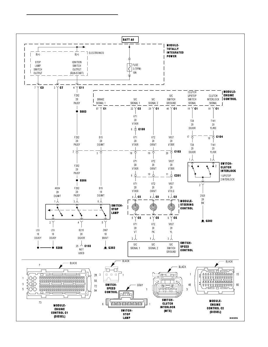
P0501–VEHICLE SPEED SENSOR #1 PERFORMANCE

For a complete wiring diagram Refer to Section 8W

PM

ENGINE ELECTRICAL DIAGNOSTICS - DIESEL

9 - 1143

When Monitored:
Continuously while the system is active.

Set Condition:
There is an error in the vehicle speed message received over the CAN Bus from the Anti-lock Brake Module.

Possible Causes

INTERMITTENT DTC

CAN BUS OPEN OR SHORTED CONDITION

ANTI-LOCK BRAKE MODULE

ENGINE CONTROL MODULE (ECM)

Always perform the Pre-Diagnostic Troubleshooting procedure before proceeding. (Refer to 9 - ENGINE -
DIAGNOSIS AND TESTING)

Diagnostic Test

1.

ACTIVE DTC

NOTE: Diagnose all CAN B and C communication DTCs before continuing.
Test drive the vehicle

With a scan tool, view DTCs.

Is the status Active for this DTC?

Yes

>> Go To 2

No

>> Refer to the INTERMITTENT CONDITION Diagnostic Procedure. (Refer to 9 - ENGINE - DIAGNOSIS

AND TESTING)

Perform the ECM Verification Test Ver. 1.

2.

DTCS PRESENT IN THE ANTI-LOCK BRAKE MODULE

With a scan tool check for DTCs in the Anti-lock Brake Module.

Are there any DTCs active in the Anti-lock Brake Module at this time?

Yes

>> Repair Anti-Lock Brake Module DTC’s.

No

>> Replace and program the Engine Control Module (ECM) in accordance with the Service Information.

Perform the ECM Verification Test Ver. 1. (Refer to 9 - ENGINE - DIAGNOSIS AND TESTING)

9 - 1144

ENGINE ELECTRICAL DIAGNOSTICS - DIESEL

PM

P0504-BRAKE SWITCH SIGNAL CIRCUITS PLAUSIBILITY WITH REDUNDANT
CONTACT

PM

ENGINE ELECTRICAL DIAGNOSTICS - DIESEL

9 - 1145

For a complete wiring diagram Refer to Section 8W

When Monitored:
With the ignition on.

Set Condition:
The Brake Switch Signal 1 and Brake Switch Signal 2 inputs to the ECM do not agree for 2 minutes.

Possible Causes

INTERMITTENT CONDITION

BRAKE SWITCH SIGNAL 2 - SWITCH 2 CKT OPEN

(A924) FUSED B+ CIRCUIT OPEN

(B215) BRAKE SWITCH SIGNAL 2 CIRCUIT SHORTED TO GROUND

BRAKE SWITCH SIGNAL 1 - SWITCH 1 CKT OPEN

(B215) BRAKE SWITCH SIGNAL 2 CIRCUIT OPEN

(Z967) STOP LAMP SWITCH GROUND CIRCUIT OPEN

(B15) BRAKE SWITCH SIGNAL 1 CIRCUIT SHORTED TO VOLTAGE

(B15) BRAKE SWITCH SIGNAL 1 CIRCUIT OPEN

ENGINE CONTROL MODULE - BRAKE SWITCH SIGNAL 2

ENGINE CONTROL MODULE - INTERNAL

ENGINE CONTROL MODULE - BRAKE SWITCH SIGNAL 1

Always perform the Pre-Diagnostic Troubleshooting procedure before proceeding. (Refer to 9 - ENGINE -
DIAGNOSIS AND TESTING)

Diagnostic Test

1.

CHECK THE BRAKE SWITCH SIGNAL 1 STATUS

Turn the ignition on.

While observing the BRAKE SWITCH SIGNAL 1 status on the scan tool display, press and release the brake pedal
several times.

Does the scan tool display BRAKE SWITCH SIGNAL1: PRESSED and RELEASED for the appropriate
pedal position?

Yes

>> Go To 2

No

>> Go To 11

2.

CHECK THE BRAKE SWITCH SIGNAL 2 STATUS

While observing the BRAKE SWITCH SIGNAL 2 status on the scan tool display, press and release the brake pedal
several times.

Does the scan tool display BRAKE SWITCH SIGNAL 2: PRESSED and RELEASED for the appropriate
pedal position

Yes

>> Go To 3

No

>> Go To 4

9 - 1146

ENGINE ELECTRICAL DIAGNOSTICS - DIESEL

PM


Content   ..  962  963  964  965   ..