Dodge Caliber. Manual - part 939


  Index      Dodge     Dodge Caliber - service repair manual 2007 year


Search            


Content   ..  937  938  939  940   ..


Dodge Caliber. Manual - part 939


7.

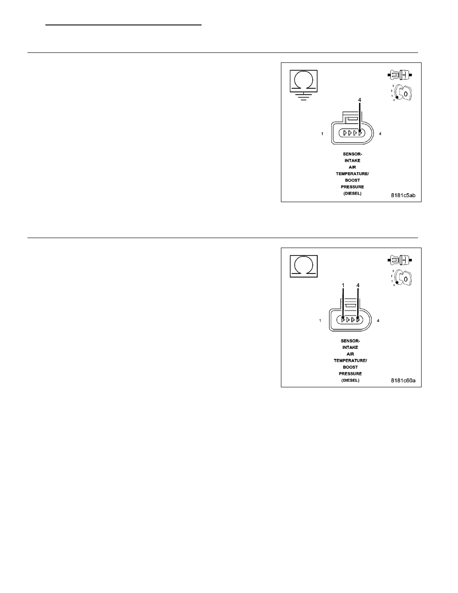
(K37) BOOST PRESSURE SENSOR SIGNAL CIRCUIT SHORTED TO GROUND

Turn the ignition off.

Disconnect the Engine Control Module (ECM) harness connector.

Measure the resistance between ground and the (K37) Boost Pressure
Sensor Signal circuit in the Intake Air Temp/Boost Pressure Sensor har-
ness connector.

Is the resistance above 1000 ohms?

Yes

>> Go to 8

No

>> Repair the (K37) Boost Pressure Sensor Signal circuit for a

short to ground.

Perform the ECM Verification Test Ver. 1. (Refer to 9 -
ENGINE - DIAGNOSIS AND TESTING)

8.

(K37) BOOST PRESSURE SENSOR SIGNAL CIRCUIT SHORTED TO (K656) BOOST PRESSURE SENSOR
GROUND CIRCUIT

Measure the resistance between the (K37) Boost Pressure Sensor Sig-
nal circuit and the (K656) Boost Pressure Sensor Ground circuit in the
Intake Air Temp/Boost Pressure Sensor harness connector.

Is the resistance above 1000 ohms?

Yes

>> Go to 9

No

>> Repair the (K37) Boost Pressure Sensor Signal circuit for a

short to the (K656) Boost Pressure Sensor Ground circuit.

Perform the ECM Verification Test Ver. 1. (Refer to 9 -
ENGINE - DIAGNOSIS AND TESTING)

PM

ENGINE ELECTRICAL DIAGNOSTICS - DIESEL

9 - 1043

9.

(K37) BOOST PRESSURE SENSOR SIGNAL CIRCUIT OPEN OR HIGH RESISTANCE

Measure the resistance of the (K37) Boost Pressure Sensor Signal cir-
cuit between the Intake Air Temp/Boost Pressure Sensor harness con-
nector and the Engine Control Module (ECM) harness connector.

Is the resistance below 10.0 ohms?

Yes

>> Go to 10

No

>> Repair the (K37) Boost Pressure Sensor Signal circuit for

an open circuit or high resistance.

Perform the ECM Verification Test Ver. 1. (Refer to 9 -
ENGINE - DIAGNOSIS AND TESTING)

10.

ENGINE CONTROL MODULE (ECM)

Using the wiring diagram/schematic as a guide, inspect the wiring and connectors between the Boost Pressure Sen-
sor and the Engine Control Module (ECM).

Look for any chafed, pierced, pinched, or partially broken wires.

Look for broken, bent, pushed out or corroded terminals.

Monitor the scan tool data relative to this circuit and wiggle test the wiring and connectors.

Look for the data to change or for the DTC to reset during the wiggle test.

Refer to any Technical Service Bulletins that may apply.

Were any problems found?

Yes

>> Repair as necessary.

Perform the ECM Verification Test Ver. 1. (Refer to 9 - ENGINE - DIAGNOSIS AND TESTING)

No

>> Replace the Engine Control Module (ECM) in accordance with the Service Information.

Perform the ECM Verification Test Ver. 1. (Refer to 9 - ENGINE - DIAGNOSIS AND TESTING)

9 - 1044

ENGINE ELECTRICAL DIAGNOSTICS - DIESEL

PM

P0238-TURBO BOOST PRESSURE SENSOR CIRCUIT HIGH

For a complete wiring diagram Refer to Section 8W

PM

ENGINE ELECTRICAL DIAGNOSTICS - DIESEL

9 - 1045

When Monitored:
With the ignition on.

Set Condition:
The (K37) Boost Pressure Sensor Signal circuit voltage is above 4.85 volts for 0.5 second.

Possible Causes

INTERMITTENT DTC

(K854) BOOST PRESSURE SENSOR 5 VOLT SUPPLY CIRCUIT SHORTED TO VOLTAGE

(K37) BOOST PRESSURE SENSOR SIGNAL CIRCUIT SHORTED TO VOLTAGE

(K656) BOOST PRESSURE SENSOR GROUND CIRCUIT SHORTED TO VOLTAGE

(K37) BOOST PRESSURE SENSOR SIGNAL CIRCUIT OPEN OR HIGH RESISTANCE

(K656) BOOST PRESSURE SENSOR GROUND CIRCUIT OPEN OR HIGH RESISTANCE

BOOST PRESSURE SENSOR

ENGINE CONTROL MODULE (ECM)

Always perform the Pre-Diagnostic Troubleshooting procedure before proceeding. (Refer to 9 - ENGINE -
DIAGNOSIS AND TESTING)

Diagnostic Test

1.

DTC IS ACTIVE

Ignition on, engine not running.

With the scan tool, Clear DTCs in the Engine Control Module (ECM).

Monitor the scan tool for at least two minutes.

Cycle the ignition key off and on several times, leaving the ignition on for at least 10 seconds at a time.

Start the engine.

Allow the engine to reach normal operating temperature.

With the scan tool, select View DTCs.

Is the status Active for this DTC?

Yes

>> Go To 2

No

>> Refer to the *CHECKING FOR AN INTERMITTENT DTC Diagnostic Procedure. (Refer to 9 - ENGINE -

DIAGNOSIS AND TESTING)

2.

(K854) BOOST PRESSURE SENSOR 5 VOLT SUPPLY CIRCUIT SHORTED TO VOLTAGE

Turn the ignition off.

Disconnect the Intake Air Temp/Boost Pressure Sensor harness connec-
tor.

Disconnect the Engine Control Module (ECM) harness connector.

Remove the Main Relay.

Connect a jumper wire between cavity B7 and cavity B9 of the Main
Relay Connector.

Turn the ignition on.

Measure the voltage of the (K854) Boost Pressure Sensor 5 Volt Supply
circuit in the Intake Air Temp/Boost Pressure Sensor harness connector.

Is there any voltage present?

Yes

>> Repair the (K854) Boost Pressure Sensor 5 Volt Supply cir-

cuit for a short to voltage.

Perform the ECM Verification Test Ver. 1. (Refer to 9 -
ENGINE - DIAGNOSIS AND TESTING)

No

>> Go to 3

9 - 1046

ENGINE ELECTRICAL DIAGNOSTICS - DIESEL

PM


Content   ..  937  938  939  940   ..