Dodge Caliber. Manual - part 846


  Index      Dodge     Dodge Caliber - service repair manual 2007 year


Search            


Content   ..  844  845  846  847   ..


Dodge Caliber. Manual - part 846


3.

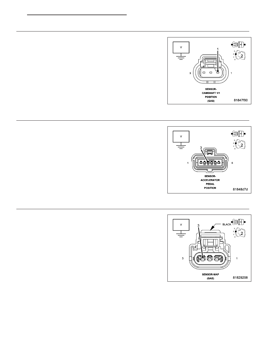
ACCELERATOR PEDAL POSITION SENSOR

Turn the ignition off.

Connect the APP Sensor harness connector.

Disconnect the Camshaft 1/1 Position Sensor harness connector.

Turn the ignition on.

Measure the voltage of the (K857) 5 Volt Supply circuit in the Camshaft
1/1 Position Sensor harness connector.

Is the voltage below 4.8 volts?

Yes

>> Replace the Accelerator Pedal Position Sensor.

Perform the PCM Verification Test Ver. 1 (Refer to 9 -
ENGINE - DIAGNOSIS AND TESTING)

No

>> Go to 9

4.

CAMSHAFT 1/1 POSITION SENSOR

Turn the ignition off.

Disconnect the Camshaft 1/1 Position Sensor harness connector.

Turn the ignition on.

Measure the voltage of the (K858) 5 Volt Supply circuit in the APP Sen-
sor harness connector.

Is the voltage above 4.8 volts?

Yes

>> Replace the Camshaft 1/1 Position Sensor.

Perform the PCM Verification Test Ver. 1 (Refer to 9 -
ENGINE - DIAGNOSIS AND TESTING)

No

>> Go to 5

5.

MAP SENSOR

Turn the ignition off.

Disconnect the MAP Sensor harness connector.

Turn the ignition on.

Measure the voltage of the (K858) 5 Volt Supply circuit.

Is the voltage above 4.8 volts?

Yes

>> Replace the MAP Sensor.

Perform the PCM Verification Test Ver. 1 (Refer to 9 -
ENGINE - DIAGNOSIS AND TESTING)

No

>> Go to 6

PM

ENGINE ELECTRICAL DIAGNOSTICS - GPEC

9 - 671

6.

MANIFOLD FLOW VALVE

Turn the ignition off.

Disconnect the Manifold Flow Valve harness connector.

Turn the ignition on.

Measure the voltage of the (K857) 5 Volt Supply circuit.

Is the voltage above 4.8 volts?

Yes

>> Replace the Manifold Flow Valve in accordance with the

Service Information.

Perform the PCM Verification Test Ver. 1 (Refer to 9 -
ENGINE - DIAGNOSIS AND TESTING)

No

>> Go to 7

7.

5-VOLT SUPPLY CIRCUIT SHORTED TO GROUND

NOTE: All sensors connected to the (K857) 5 volt supply circuit
and the (K858) 5 volt supply circuit must be disconnected.
Turn the ignition off.

Disconnect the PCM harness connectors.

Measure the resistance between ground and the (K857) 5 Volt Supply
circuit.

Measure the resistance between ground and the (K858) 5 Volt Supply
circuit.

Is the resistance above 1000 ohms for both circuits?

Yes

>> Go to 8

No

>> Repair the 5 Volt Supply circuit for a short to ground.

Perform the PCM Verification Test Ver. 1 (Refer to 9 -
ENGINE - DIAGNOSIS AND TESTING)

8.

5-VOLT SUPPLY CIRCUIT OPEN OR HIGH RESISTANCE

NOTE: All sensors connected to the (K857) 5 volt supply circuit and the (K858) 5 volt supply circuit must be
disconnected.
Turn the ignition off.

Measure the resistance of the (K857) 5 Volt Supply circuit between the Camshaft 1/1 Position Sensor harness con-
nector and the PCM harness connector.

Measure the resistance of the (K857) 5 Volt Supply circuit between the MAP Sensor harness connector and the
PCM harness connector.

Measure the resistance of the (K857) 5 Volt Supply circuit between the Manifold Flow Valve harness connector and
the PCM harness connector.

Measure the resistance of the (K858) 5 Volt Supply circuit between the Accelerator Pedal Position Sensor harness
connector and the PCM harness connector.

Is the resistance below 5.0 ohms for all of the circuits?

Yes

>> Go to 9

No

>> Repair the 5 Volt Supply circuit for an open circuit or high resistance.

Perform the PCM Verification Test Ver. 1 (Refer to 9 - ENGINE - DIAGNOSIS AND TESTING)

9 - 672

ENGINE ELECTRICAL DIAGNOSTICS - GPEC

PM

9.

POWERTRAIN CONTROL MODULE (PCM)

Inspect the (K857) 5 Volt Supply circuit between the Camshaft 1/1 Position Sensor harness connector and the PCM
harness connector.

Inspect the (K857) 5 Volt Supply circuit between the MAP Sensor harness connector and the PCM harness con-
nector.

Inspect the (K857) 5 Volt Supply circuit between the Manifold Flow Valve harness connector and the PCM harness
connector.

Inspect the (K858) 5 Volt Supply circuit between the Accelerator Pedal Position Sensor harness connector and the
PCM harness connector.

Inspect all PCM power and ground circuits.

Look for any chafed, pierced, pinched, or partially broken wires.

Look for broken, bent, pushed out or corroded terminals.

Refer to any Technical Service Bulletins that may apply.

Were any problems found?

Yes

>> Repair as necessary.

Perform the PCM Verification Test Ver. 1 (Refer to 9 - ENGINE - DIAGNOSIS AND TESTING)

No

>> Replace the PCM in accordance with the Service Information.

Perform the PCM Verification Test Ver. 1 (Refer to 9 - ENGINE - DIAGNOSIS AND TESTING)

PM

ENGINE ELECTRICAL DIAGNOSTICS - GPEC

9 - 673

P1696-EEPROM MEMORY WRITE DENIED/INVALID

For a complete wiring diagram Refer to Section 8W.

When Monitored:
Continuously with the ignition on.

Set Condition:
An attempt to program/write to the internal EEPROM failed. Also checks at powerdown. One Trip Fault. Three
good trips to turn off the MIL.

Possible Causes

PCM

Always perform the Pre-Diagnostic Troubleshooting procedure before proceeding. (Refer to 9 - ENGINE -
DIAGNOSIS AND TESTING).

Diagnostic Test

1.

SCAN TOOL DISPLAYS A WRITE FAILURE

With a scan tool, perform the SRI Memory Test.

Does scan tool display Write Failure?

Yes

>> Replace and program the Powertrain Control Module per Service Information.

Perform the POWERTRAIN VERIFICATION TEST. (Refer to 9 - ENGINE - STANDARD PROCEDURE)

No

>> Go To 2

2.

SCAN TOOL DISPLAYS A WRITE REFUSED

With the a scan tool, perform the SRI Memory Test.

Does the scan tool display Write Refused?

Yes

>> Go To 3

No

>> Go To 4

3.

PCM REFUSED 2ND TEST

With a scan tool, perform the SRI Memory Test a third time.

NOTE: Retest the SRI Memory two more times.

Does the scan tool display Write Refused again?

Yes

>> Replace and program the Powertrain Control Module per Service Information.

Perform the POWERTRAIN VERIFICATION TEST. (Refer to 9 - ENGINE - STANDARD PROCEDURE)

No

>> Test Complete.

4.

SCAN TOOL DISPLAYS SRI MILEAGE INVALID

With a scan tool, perform the SRI Memory Test.

Does the scan tool display SRI Mileage Invalid?

Yes

>> Update the mileage and retest the SRI Memory.

Perform the POWERTRAIN VERIFICATION TEST. (Refer to 9 - ENGINE - STANDARD PROCEDURE)

No

>> Go To 5

9 - 674

ENGINE ELECTRICAL DIAGNOSTICS - GPEC

PM


Content   ..  844  845  846  847   ..